IOB-I2C-PCA9685-PWM
IOB I2C PCA9685 PWN driver
Specifications
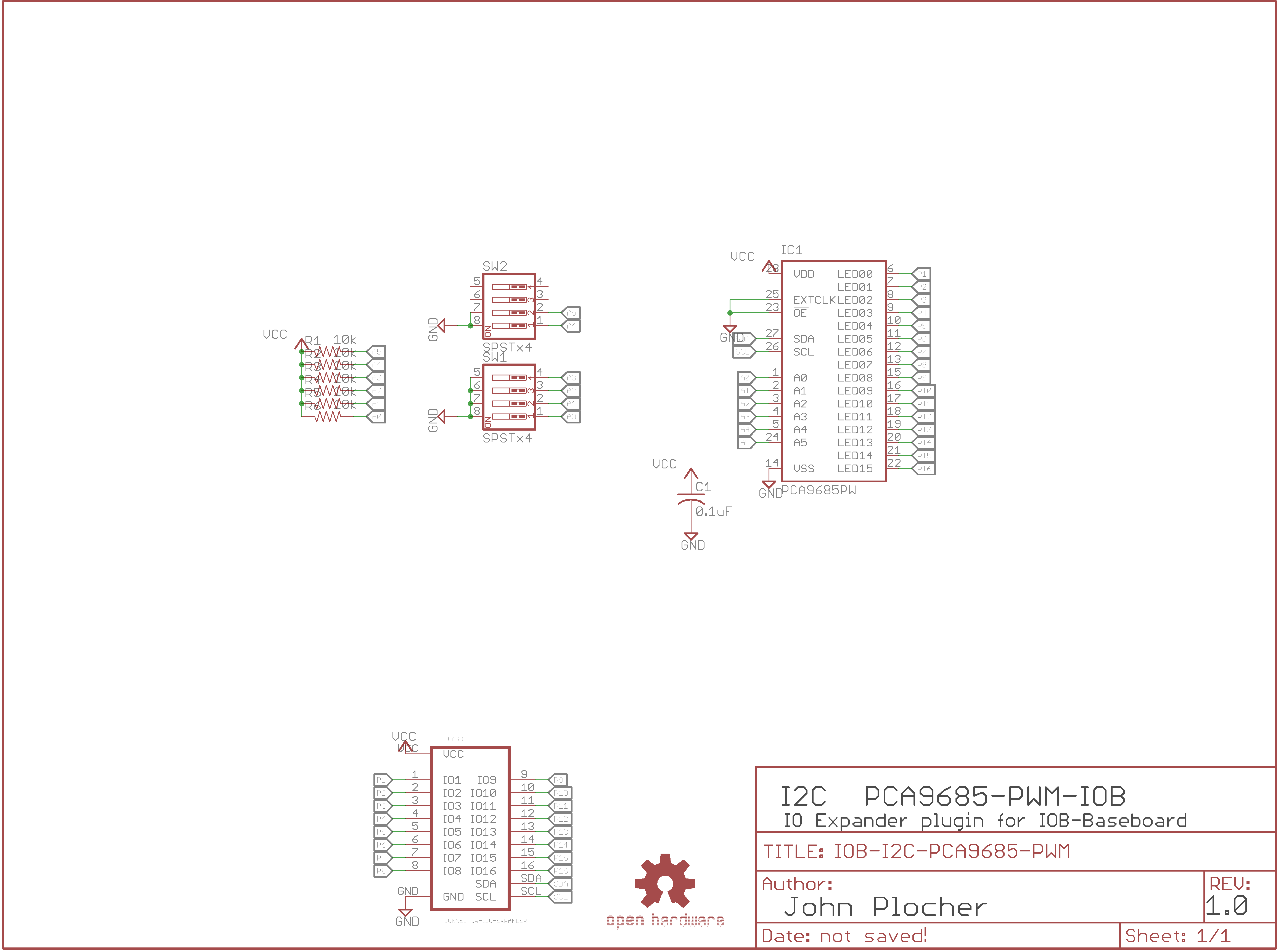
- The PCA9685 is an i2c-controlled PWM driver with a built in free running clock.
- The board is 5V compliant, which means you can control it from a 3.3V microcontroller and still safely drive up to 6V outputs (for LEDS and Servos)
- 6 address select pins support up to 62 of these on a single I2C bus
- Adjustable frequency PWM up to about 1.6 KHz
- 12-bit resolution for each output
- Configurable push-pull or open-drain output
- Output enable pin to quickly disable all the outputs
Communication Protocol
```C++ Simple I2C 16-bit Reads and Writes:
void I2Cexpander::init9685(uint8_t i2caddr, uint16_t dir) {
if (i2caddr < base9685) {
_i2c_address = i2caddr + base9685;
} else {
_i2c_address = i2caddr;
}
Wire.beginTransmission(_i2c_address);
Wire.write(PCA9685_MODE1);
Wire.write(PCA9685_MODE1_SLEEP);
Wire.endTransmission();
delay(1);
// Set precaler: float prescaleval = ((_oscillator_freq / (freq * 4096.0)) + 0.5) - 1;
// max 255, min 3
// internal _oscillator_freq is 25MHz
Wire.beginTransmission(_i2c_address);
Wire.write(PCA9685_PRESCALE);
Wire.write(6); // a value of 6 is about a 1000 Hz refresh rate Servos need 60Hz: 101
Wire.endTransmission();
delay(1);
Wire.beginTransmission(_i2c_address);
Wire.write(PCA9685_MODE1);
Wire.write(PCA9685_MODE1_RESTART | PCA9685_MODE1_AUTOINC | PCA9685_MODE1_ALLCALL);
Wire.endTransmission();
delay(1);
Wire.beginTransmission(_i2c_address);
Wire.write(PCA9685_MODE2);
Wire.write(PCA9685_MODE2_TOTEM | PCA9685_MODE2_OEOFF);
Wire.endTransmission();
delay(1);
}
// read uses the config value to distinguish which LED to read/write
uint32_t I2Cexpander::read9685() {
uint32_t data = 0;
uint16_t startdata = 0;
uint16_t stopdata = 0;
Wire.beginTransmission(_i2c_address);
Wire.write(PCA9685_BASE_LED0 + (_config * 4));
int n = Wire.endTransmission(false);
if (! ((n == 0) || (n ==7)) ) {
return (_last);
}
Wire.requestFrom(_i2c_address, (uint8_t)4, (uint8_t)1);
startdata = Wire.read();
startdata |= (Wire.read() « 8);
stopdata = Wire.read();
stopdata |= (Wire.read() « 8);
if (stopdata == startdata) data = 0;
else if (stopdata < startdata) data = startdata + stopdata & 0x0FFF;
else data = stopdata - startdata;
return data;
}
void I2Cexpander::write9685(uint32_t data) {
/*
* The chip has a freerunning counter (0..4095, 0x0000 to 0x0FFF)
* LED#_ON_H/L bits 0..11 are start ‘time’ for turn on
* Bit 12 (0x1000) means CONSTANT ON, unless OFF bit is also set
* LED#_OFF_H/L bits 0..11 are start ‘time’ for turn off
* Bit 12 (0x1000) means CONSTANT OFF, overrides any ON setting
*/
data = data & 0x0FFF;
//  Stagger starting phase to ensure each string is independent, to reduce power supply spiking
int start = (_config * 0x0F); // use LED num as beginning count...

unsigned int end = (data + start) % 0x0FFF;		// 12 bits = 4096
int b1 = (start     ) & 0x00FF; // low byte ...
int b2 = (start >> 8) & 0x000F; // ... and high nibble
int e1 = (end       ) & 0x00FF; // low byte ...
int e2 = (end   >> 8) & 0x000F; // ... and high nibble

if (data == 0x0FFF) {		// FULL ON
    b2 |= 0x1000;
} else if (data == 0x0000) {	// FULL OFF
    e2 |= 0x1000;
}

Wire.beginTransmission(_i2c_address);
Wire.write(PCA9685_BASE_LED0 + (_config * 4));

Wire.write(b1);
Wire.write(b2);
Wire.write(e1);
Wire.write(e2);

Wire.endTransmission();   } ``` See [I2Cexpander-lib](/pages/I2Cexpander "wikilink") for a more complete interface library.
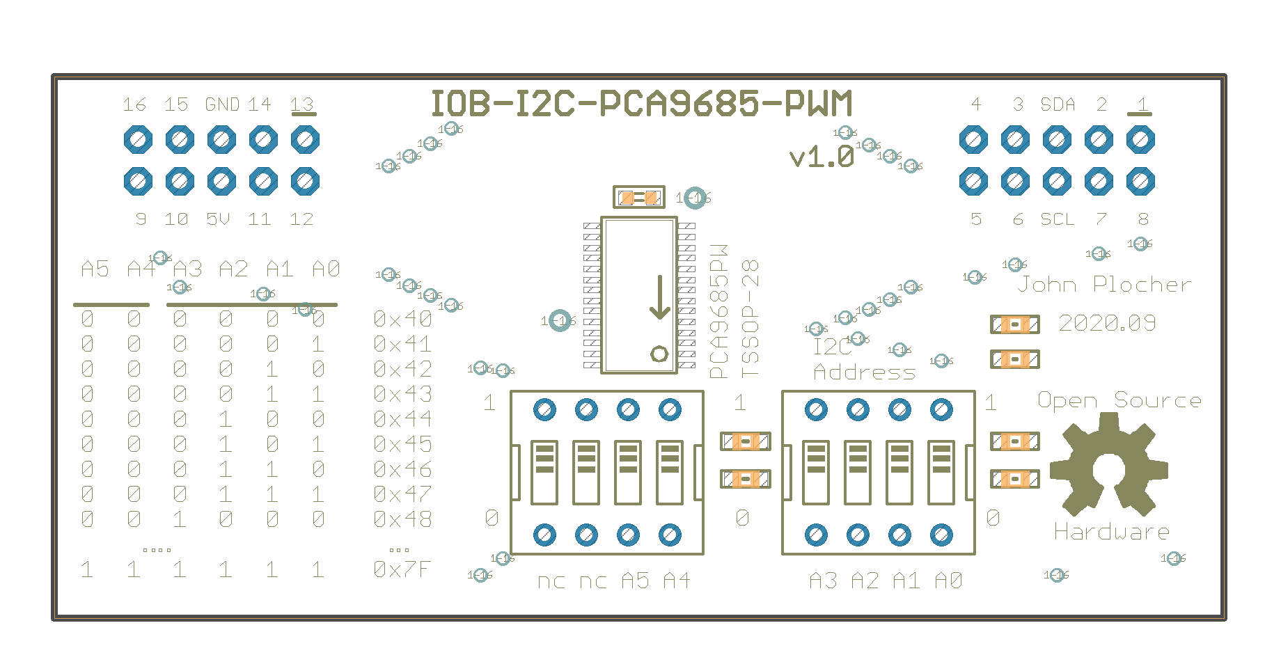
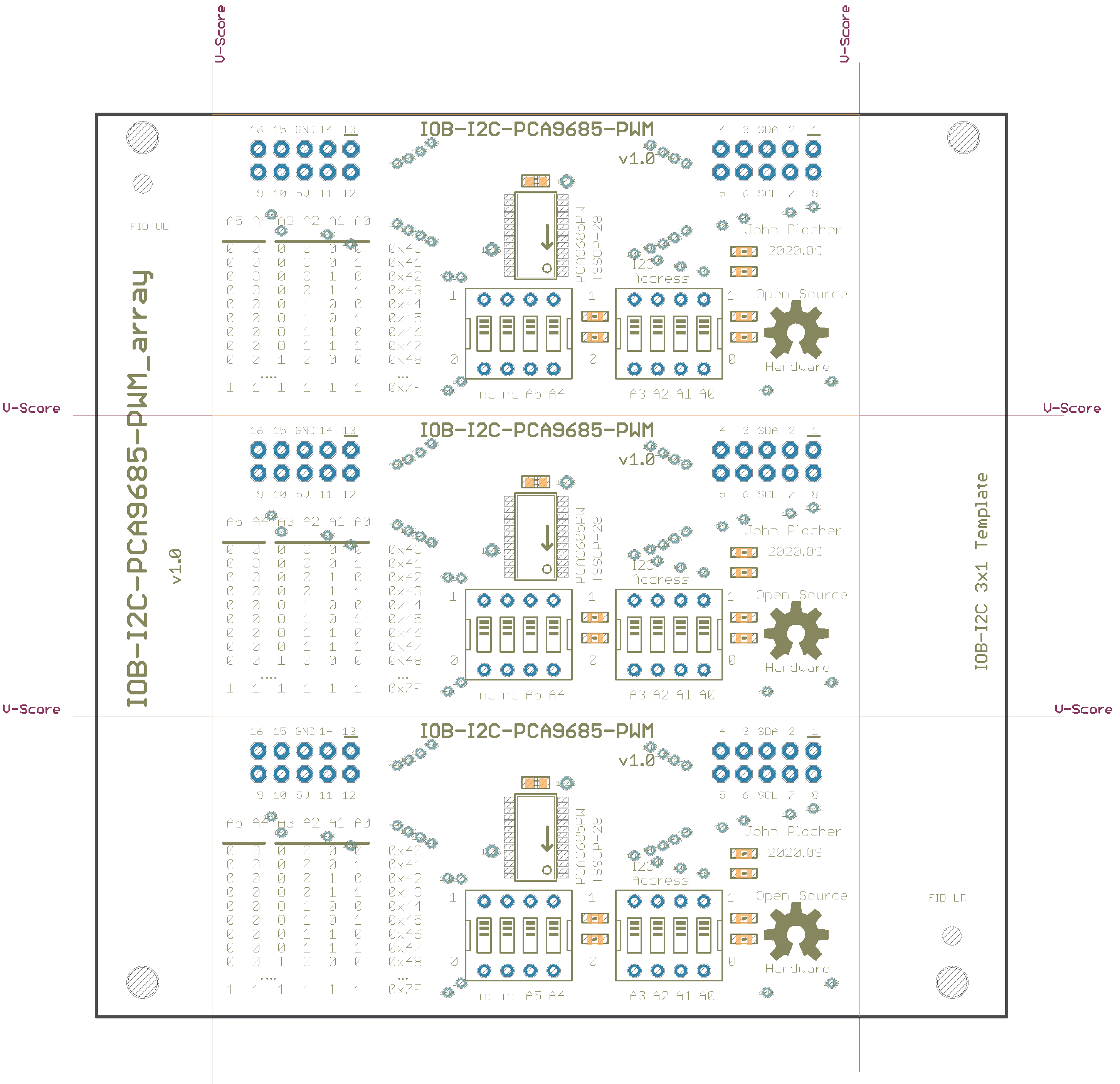
Addressing The addres selection for the PCA9685 allows for 62 devices, addresses 0x40 to 0x7F. The board has dip switches for A0 through A5, A6 is hardcoded to “1” in the chip.
A6|A5|A4|A3|A2|A1|A0|ADDRESS (HEX) :—–:|:—–:|:—–:|:—–:|:—–:|:—–:|:—–:|:—–: 1|0|0| 0|0|0|0 | 0x40 1|0|0| 0|0|0|1 | 0x41 1|0|0| 0|0|1|0 | 0x42 1|0|0| 0|0|1|1 | 0x43 1|0|0| 0|1|0|0 | 0x44 1|0|0| 0|1|0|1 | 0x45 1|0|0| 0|1|1|0 | 0x46 1|0|0| 0|1|1|1 | 0x47 1|0|0| 1|0|0|0 | 0x48 1|0|0| 1|0|0|1 | 0x49 1|0|0| 1|0|1|0 | 0x4A 1|0|0| 1|0|1|1 | 0x4B 1|0|0| 1|1|0|0 | 0x4C 1|0|0| 1|1|0|1 | 0x4D 1|0|0| 1|1|1|0 | 0x4E 1|0|0| 1|1|1|1 | 0x4F 1|0|1| 0|0|0|0 | 0x50 1|0|1| 0|0|0|1 | 0x51 1|0|1| 0|0|1|0 | 0x52 1|0|1| 0|0|1|1 | 0x53 1|0|1| 0|1|0|0 | 0x54 1|0|1| 0|1|0|1 | 0x55 1|0|1| 0|1|1|0 | 0x56 1|0|1| 0|1|1|1 | 0x57 1|0|1| 1|0|0|0 | 0x58 1|0|1| 1|0|0|1 | 0x59 1|0|1| 1|0|1|0 | 0x5A 1|0|1| 1|0|1|1 | 0x5B 1|0|1| 1|1|0|0 | 0x5C 1|0|1| 1|1|0|1 | 0x5D 1|0|1| 1|1|1|0 | 0x5E 1|0|1| 1|1|1|1 | 0x5F 1|1|0| 0|0|0|0 | 0x60 1|1|0| 0|0|0|1 | 0x61 1|1|0| 0|0|1|0 | 0x62 1|1|0| 0|0|1|1 | 0x63 1|1|0| 0|1|0|0 | 0x64 1|1|0| 0|1|0|1 | 0x65 1|1|0| 0|1|1|0 | 0x66 1|1|0| 0|1|1|1 | 0x67 1|1|0| 1|0|0|0 | 0x68 1|1|0| 1|0|0|1 | 0x69 1|1|0| 1|0|1|0 | 0x6A 1|1|0| 1|0|1|1 | 0x6B 1|1|0| 1|1|0|0 | 0x6C 1|1|0| 1|1|0|1 | 0x6D 1|1|0| 1|1|1|0 | 0x6E 1|1|0| 1|1|1|1 | 0x6F 1|1|1| 0|0|0|0 | 0x70 1|1|1| 0|0|0|1 | 0x71 1|1|1| 0|0|1|0 | 0x72 1|1|1| 0|0|1|1 | 0x73 1|1|1| 0|1|0|0 | 0x74 1|1|1| 0|1|0|1 | 0x75 1|1|1| 0|1|1|0 | 0x76 1|1|1| 0|1|1|1 | 0x77 1|1|1| 1|0|0|0 | 0x78 1|1|1| 1|0|0|1 | 0x79 1|1|1| 1|0|1|0 | 0x7A 1|1|1| 1|0|1|1 | 0x7B 1|1|1| 1|1|0|0 | 0x7C 1|1|1| 1|1|0|1 | 0x7D 1|1|1| 1|1|1|0 | 0x7E 1|1|1| 1|1|1|1 | 0x7F
|
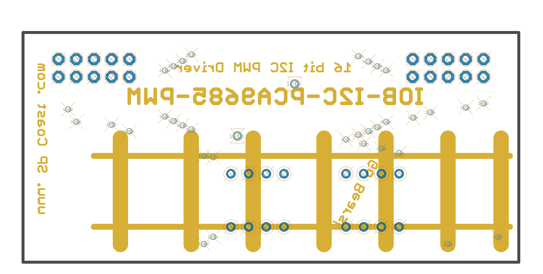
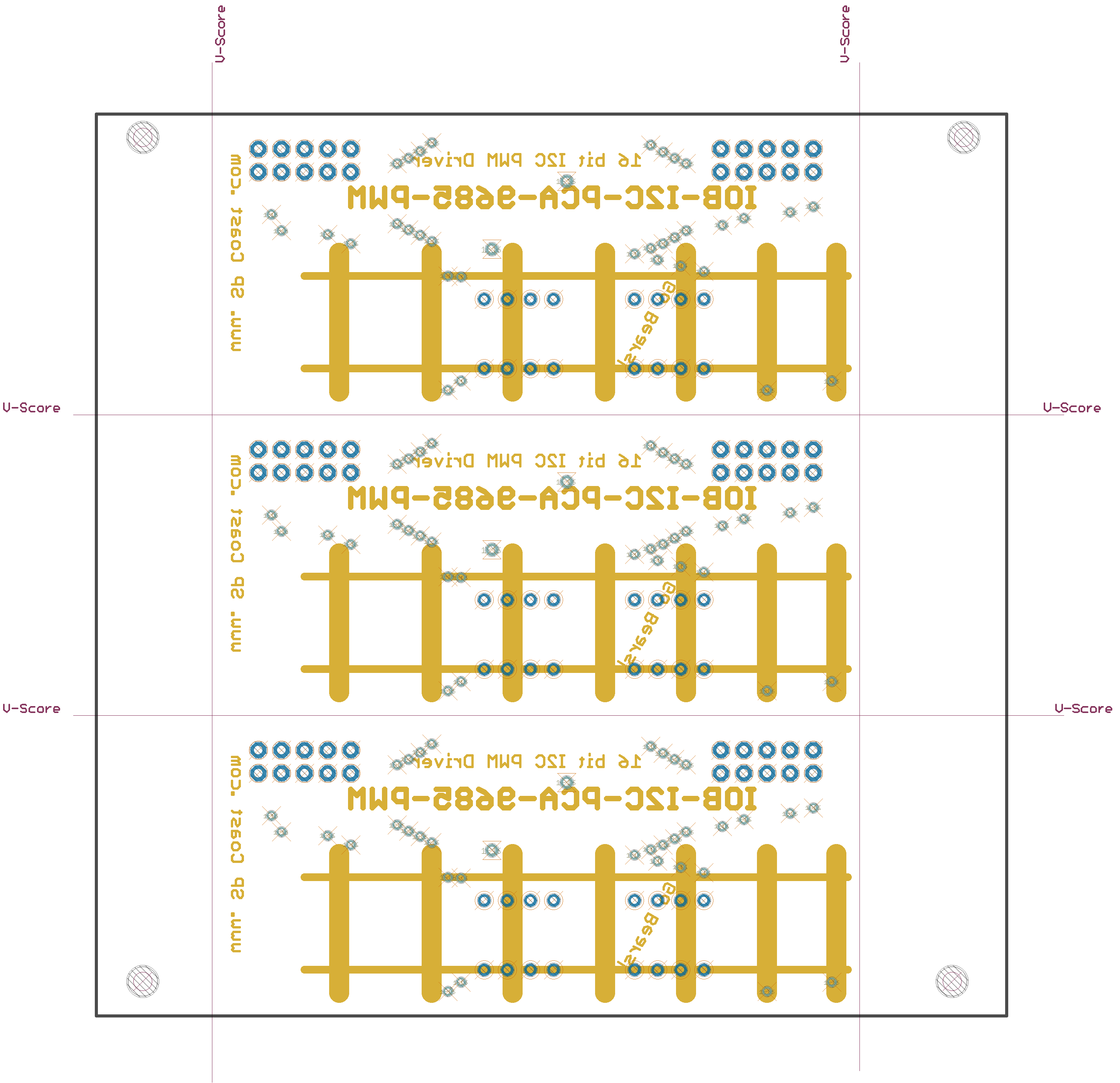
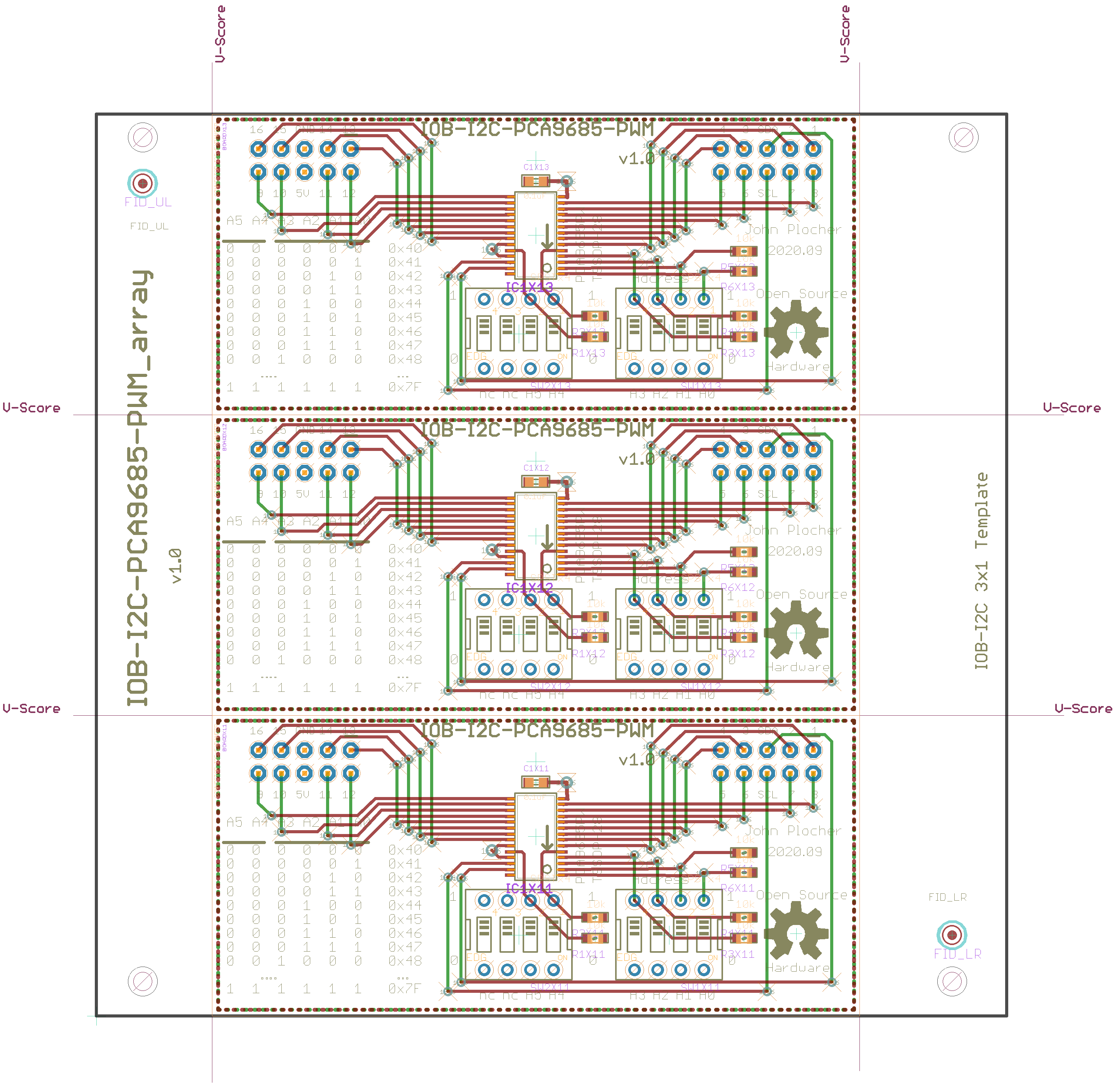
Download IOB-I2C-PCA9685-PWM_array.scr - Eagle SCRipt
IOB-I2C-PCA9685-PWM Version 1.0
First built: 2020.09
Specifications
- The PCA9685 is an i2c-controlled PWM driver with a built in free running clock.
- The board is 5V compliant, which means you can control it from a 3.3V microcontroller and still safely drive up to 6V outputs (for LEDS and Servos)
- 6 address select pins support up to 62 of these on a single I2C bus
- Adjustable frequency PWM up to about 1.6 KHz
- 12-bit resolution for each output
- Configurable push-pull or open-drain output
- Output enable pin to quickly disable all the outputs
Communication Protocol
```C++ Simple I2C 16-bit Reads and Writes:
void I2Cexpander::init9685(uint8_t i2caddr, uint16_t dir) {
if (i2caddr < base9685) {
_i2c_address = i2caddr + base9685;
} else {
_i2c_address = i2caddr;
}
Wire.beginTransmission(_i2c_address);
Wire.write(PCA9685_MODE1);
Wire.write(PCA9685_MODE1_SLEEP);
Wire.endTransmission();
delay(1);
// Set precaler: float prescaleval = ((_oscillator_freq / (freq * 4096.0)) + 0.5) - 1;
// max 255, min 3
// internal _oscillator_freq is 25MHz
Wire.beginTransmission(_i2c_address);
Wire.write(PCA9685_PRESCALE);
Wire.write(6); // a value of 6 is about a 1000 Hz refresh rate Servos need 60Hz: 101
Wire.endTransmission();
delay(1);
Wire.beginTransmission(_i2c_address);
Wire.write(PCA9685_MODE1);
Wire.write(PCA9685_MODE1_RESTART | PCA9685_MODE1_AUTOINC | PCA9685_MODE1_ALLCALL);
Wire.endTransmission();
delay(1);
Wire.beginTransmission(_i2c_address);
Wire.write(PCA9685_MODE2);
Wire.write(PCA9685_MODE2_TOTEM | PCA9685_MODE2_OEOFF);
Wire.endTransmission();
delay(1);
}
// read uses the config value to distinguish which LED to read/write
uint32_t I2Cexpander::read9685() {
uint32_t data = 0;
uint16_t startdata = 0;
uint16_t stopdata = 0;
Wire.beginTransmission(_i2c_address);
Wire.write(PCA9685_BASE_LED0 + (_config * 4));
int n = Wire.endTransmission(false);
if (! ((n == 0) || (n ==7)) ) {
return (_last);
}
Wire.requestFrom(_i2c_address, (uint8_t)4, (uint8_t)1);
startdata = Wire.read();
startdata |= (Wire.read() « 8);
stopdata = Wire.read();
stopdata |= (Wire.read() « 8);
if (stopdata == startdata) data = 0;
else if (stopdata < startdata) data = startdata + stopdata & 0x0FFF;
else data = stopdata - startdata;
return data;
}
void I2Cexpander::write9685(uint32_t data) {
/*
* The chip has a freerunning counter (0..4095, 0x0000 to 0x0FFF)
* LED#_ON_H/L bits 0..11 are start ‘time’ for turn on
* Bit 12 (0x1000) means CONSTANT ON, unless OFF bit is also set
* LED#_OFF_H/L bits 0..11 are start ‘time’ for turn off
* Bit 12 (0x1000) means CONSTANT OFF, overrides any ON setting
*/
data = data & 0x0FFF;
//  Stagger starting phase to ensure each string is independent, to reduce power supply spiking
int start = (_config * 0x0F); // use LED num as beginning count...

unsigned int end = (data + start) % 0x0FFF;		// 12 bits = 4096
int b1 = (start     ) & 0x00FF; // low byte ...
int b2 = (start >> 8) & 0x000F; // ... and high nibble
int e1 = (end       ) & 0x00FF; // low byte ...
int e2 = (end   >> 8) & 0x000F; // ... and high nibble

if (data == 0x0FFF) {		// FULL ON
    b2 |= 0x1000;
} else if (data == 0x0000) {	// FULL OFF
    e2 |= 0x1000;
}

Wire.beginTransmission(_i2c_address);
Wire.write(PCA9685_BASE_LED0 + (_config * 4));

Wire.write(b1);
Wire.write(b2);
Wire.write(e1);
Wire.write(e2);

Wire.endTransmission();   } ``` See [I2Cexpander-lib](/pages/I2Cexpander "wikilink") for a more complete interface library.
Addressing The addres selection for the PCA9685 allows for 62 devices, addresses 0x40 to 0x7F. The board has dip switches for A0 through A5, A6 is hardcoded to “1” in the chip.
A6|A5|A4|A3|A2|A1|A0|ADDRESS (HEX) :—–:|:—–:|:—–:|:—–:|:—–:|:—–:|:—–:|:—–: 1|0|0| 0|0|0|0 | 0x40 1|0|0| 0|0|0|1 | 0x41 1|0|0| 0|0|1|0 | 0x42 1|0|0| 0|0|1|1 | 0x43 1|0|0| 0|1|0|0 | 0x44 1|0|0| 0|1|0|1 | 0x45 1|0|0| 0|1|1|0 | 0x46 1|0|0| 0|1|1|1 | 0x47 1|0|0| 1|0|0|0 | 0x48 1|0|0| 1|0|0|1 | 0x49 1|0|0| 1|0|1|0 | 0x4A 1|0|0| 1|0|1|1 | 0x4B 1|0|0| 1|1|0|0 | 0x4C 1|0|0| 1|1|0|1 | 0x4D 1|0|0| 1|1|1|0 | 0x4E 1|0|0| 1|1|1|1 | 0x4F 1|0|1| 0|0|0|0 | 0x50 1|0|1| 0|0|0|1 | 0x51 1|0|1| 0|0|1|0 | 0x52 1|0|1| 0|0|1|1 | 0x53 1|0|1| 0|1|0|0 | 0x54 1|0|1| 0|1|0|1 | 0x55 1|0|1| 0|1|1|0 | 0x56 1|0|1| 0|1|1|1 | 0x57 1|0|1| 1|0|0|0 | 0x58 1|0|1| 1|0|0|1 | 0x59 1|0|1| 1|0|1|0 | 0x5A 1|0|1| 1|0|1|1 | 0x5B 1|0|1| 1|1|0|0 | 0x5C 1|0|1| 1|1|0|1 | 0x5D 1|0|1| 1|1|1|0 | 0x5E 1|0|1| 1|1|1|1 | 0x5F 1|1|0| 0|0|0|0 | 0x60 1|1|0| 0|0|0|1 | 0x61 1|1|0| 0|0|1|0 | 0x62 1|1|0| 0|0|1|1 | 0x63 1|1|0| 0|1|0|0 | 0x64 1|1|0| 0|1|0|1 | 0x65 1|1|0| 0|1|1|0 | 0x66 1|1|0| 0|1|1|1 | 0x67 1|1|0| 1|0|0|0 | 0x68 1|1|0| 1|0|0|1 | 0x69 1|1|0| 1|0|1|0 | 0x6A 1|1|0| 1|0|1|1 | 0x6B 1|1|0| 1|1|0|0 | 0x6C 1|1|0| 1|1|0|1 | 0x6D 1|1|0| 1|1|1|0 | 0x6E 1|1|0| 1|1|1|1 | 0x6F 1|1|1| 0|0|0|0 | 0x70 1|1|1| 0|0|0|1 | 0x71 1|1|1| 0|0|1|0 | 0x72 1|1|1| 0|0|1|1 | 0x73 1|1|1| 0|1|0|0 | 0x74 1|1|1| 0|1|0|1 | 0x75 1|1|1| 0|1|1|0 | 0x76 1|1|1| 0|1|1|1 | 0x77 1|1|1| 1|0|0|0 | 0x78 1|1|1| 1|0|0|1 | 0x79 1|1|1| 1|0|1|0 | 0x7A 1|1|1| 1|0|1|1 | 0x7B 1|1|1| 1|1|0|0 | 0x7C 1|1|1| 1|1|0|1 | 0x7D 1|1|1| 1|1|1|0 | 0x7E 1|1|1| 1|1|1|1 | 0x7F
|
|
|
|||
|
|
|

UNPUBLISHED
This technical documentation is licensed under the CERN Open Hardware Licence v1.2