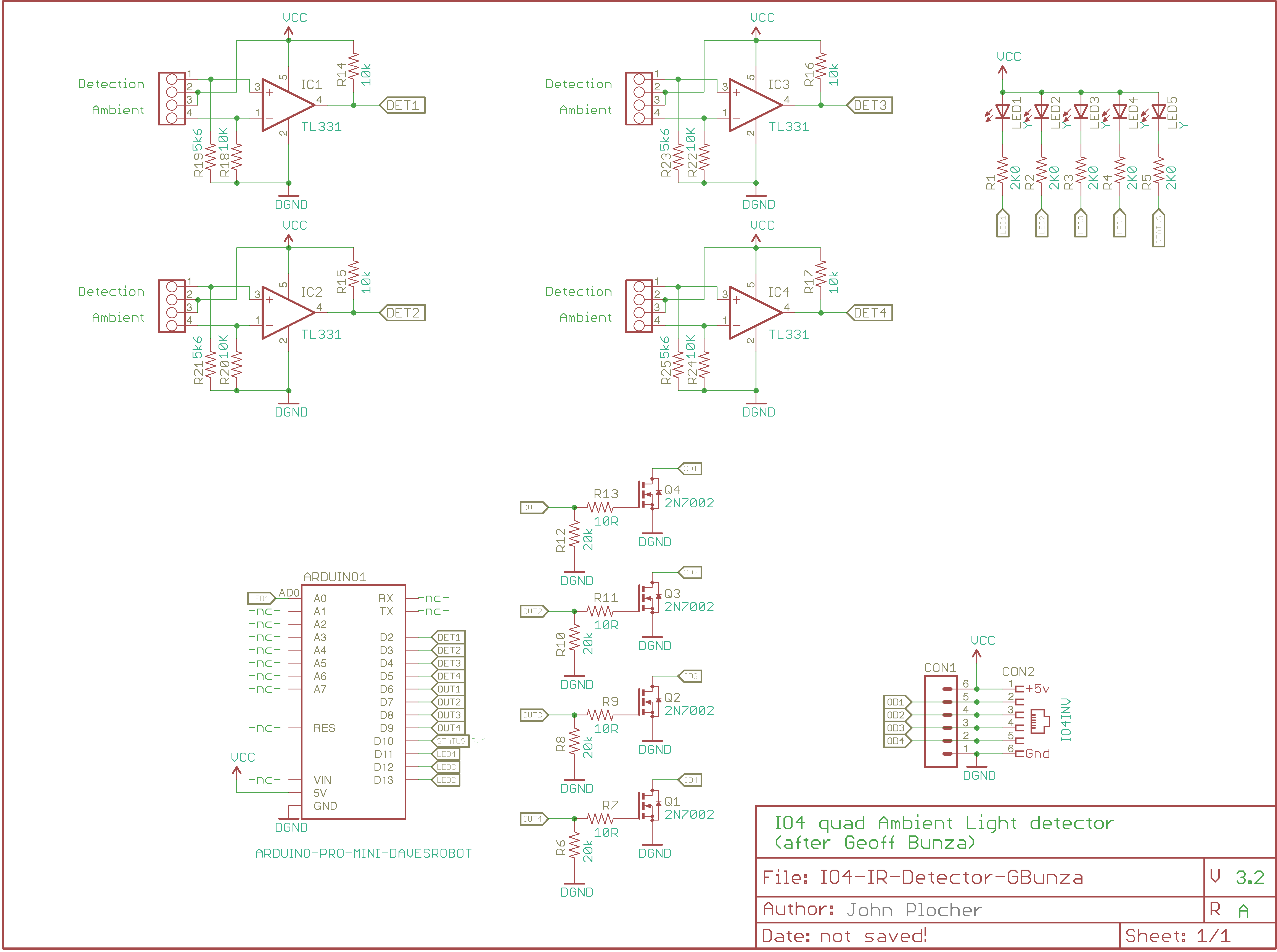
IO4-IR-Detector-GBunza
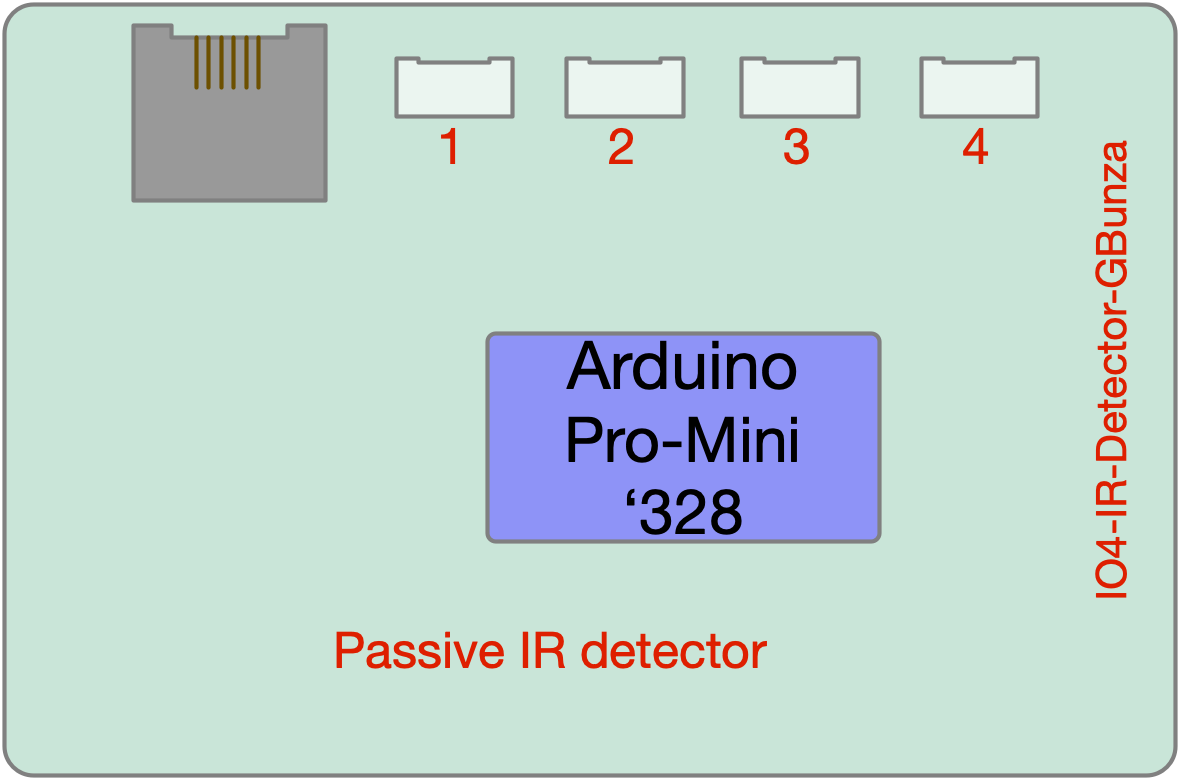
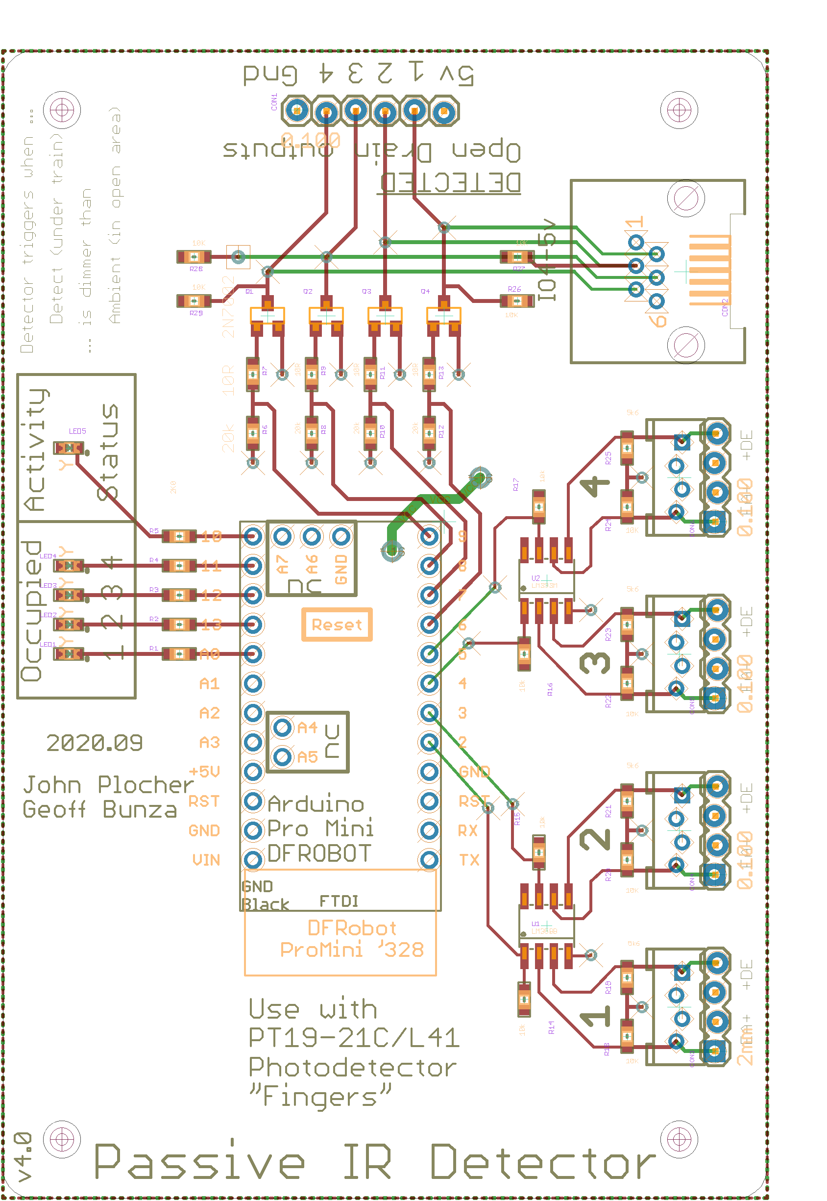
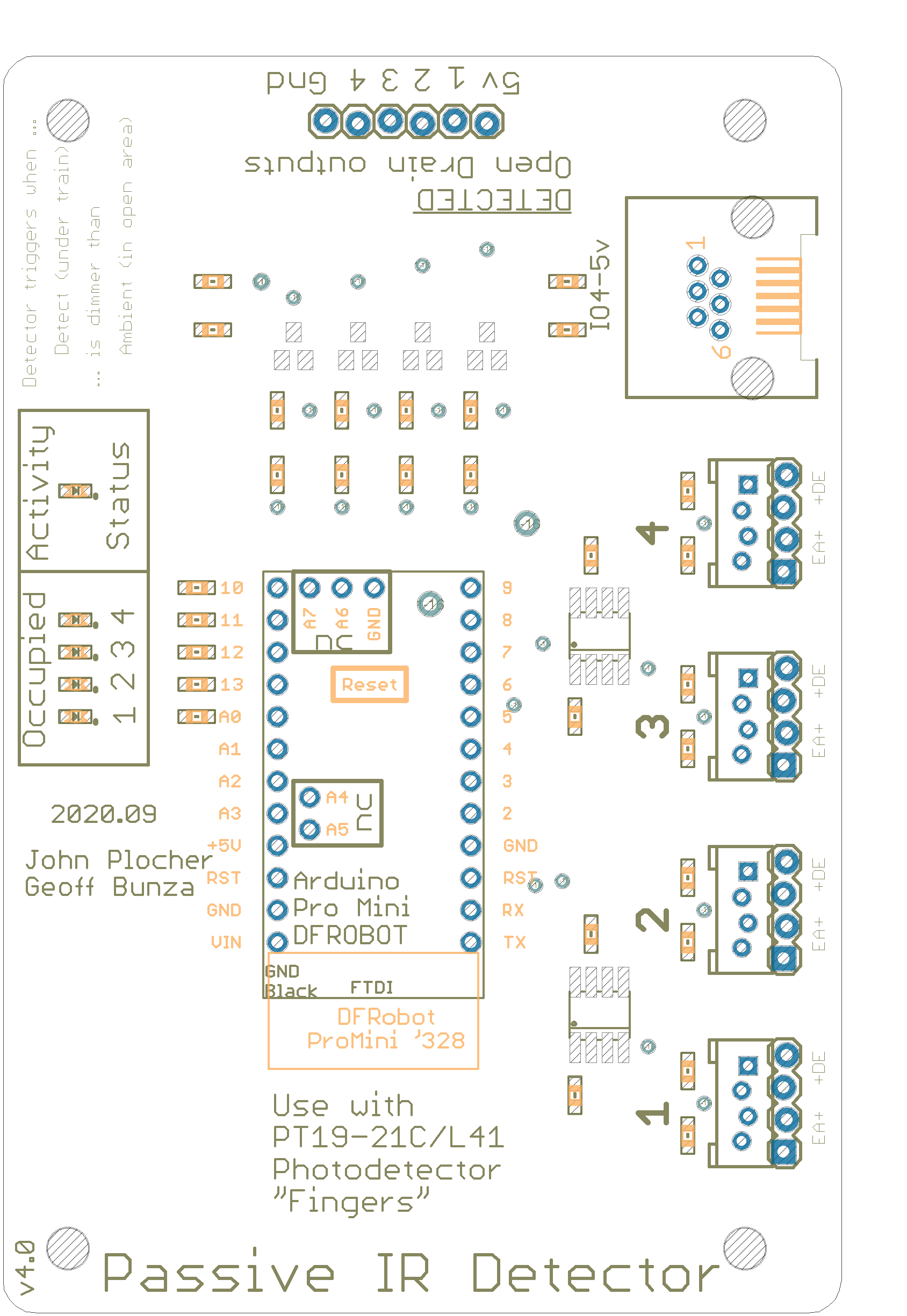
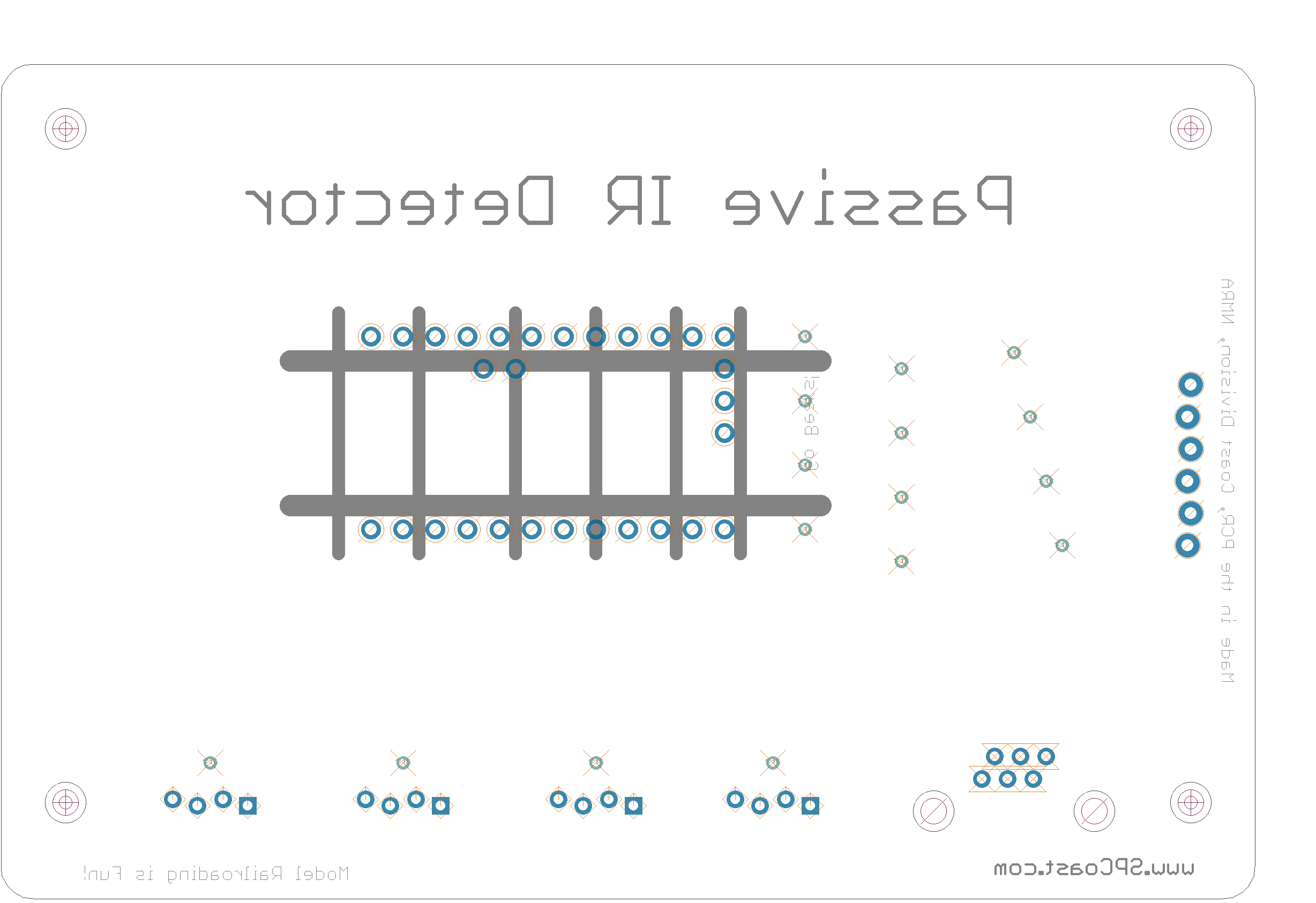
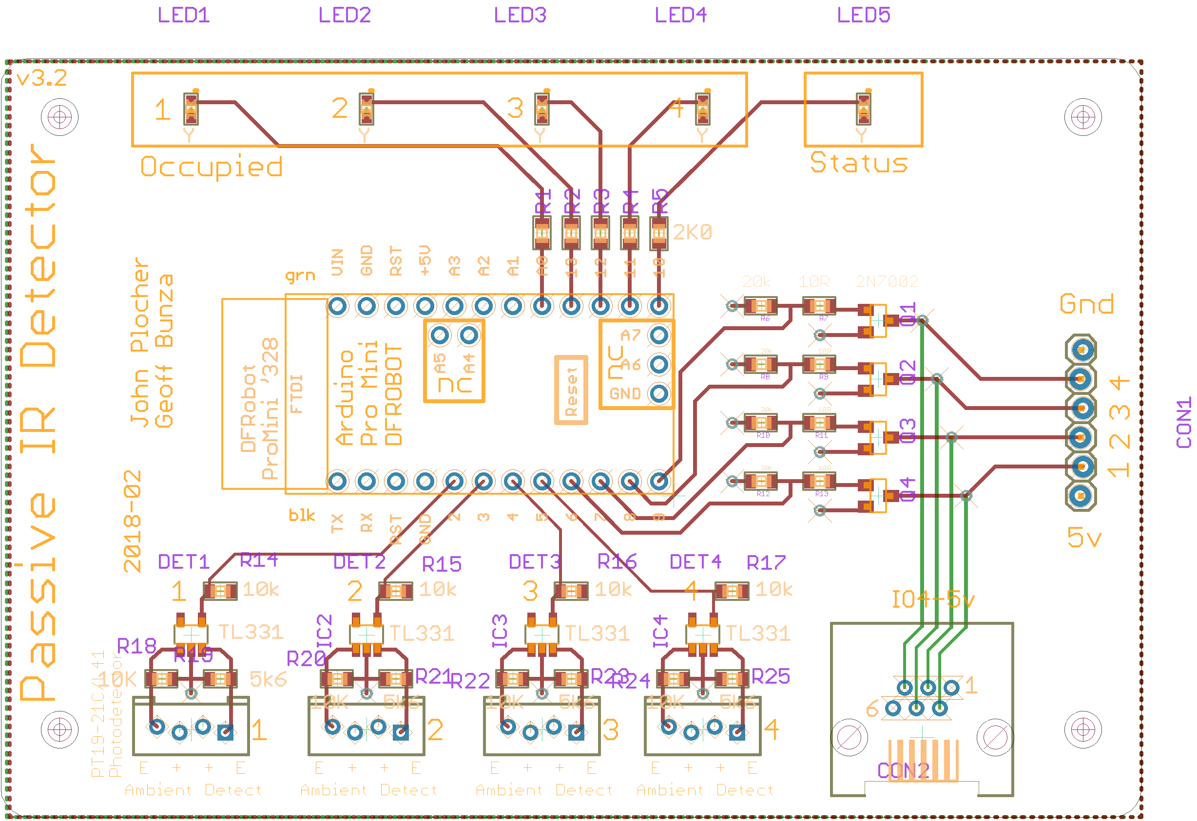
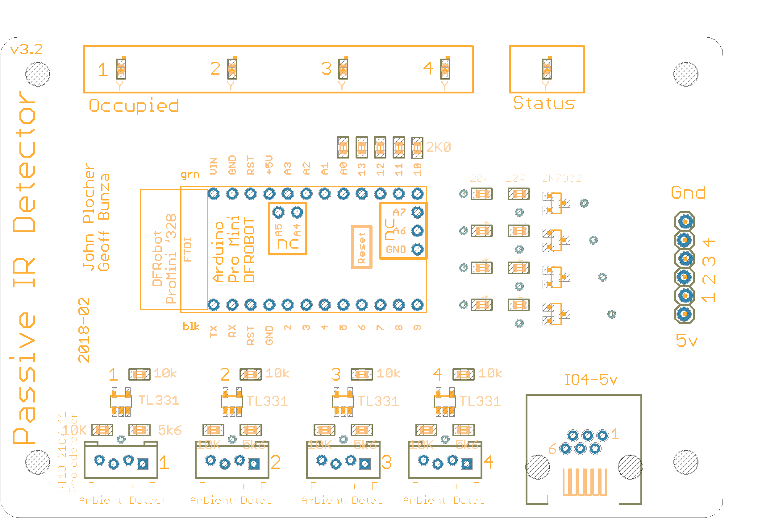
IO4 Quad Optical/IR Detector baseboard
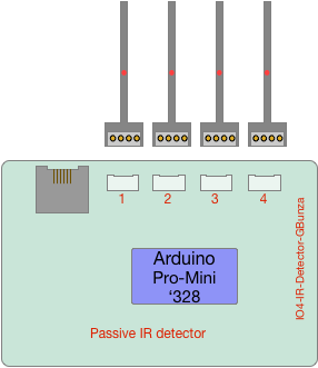
Derived from Geoff Bunza’s SMA Detector, published in his column in MRH as “SMA23 – A New DCC & DC Car & Loco Detector – Differential Absolute Position Detector (DAPD)” This version eschews “small” in favor of a remote mountable IO4 baseboard that can be mounted near the point of use, and then use sensors disguised as ties for the sensor electronics themselves.
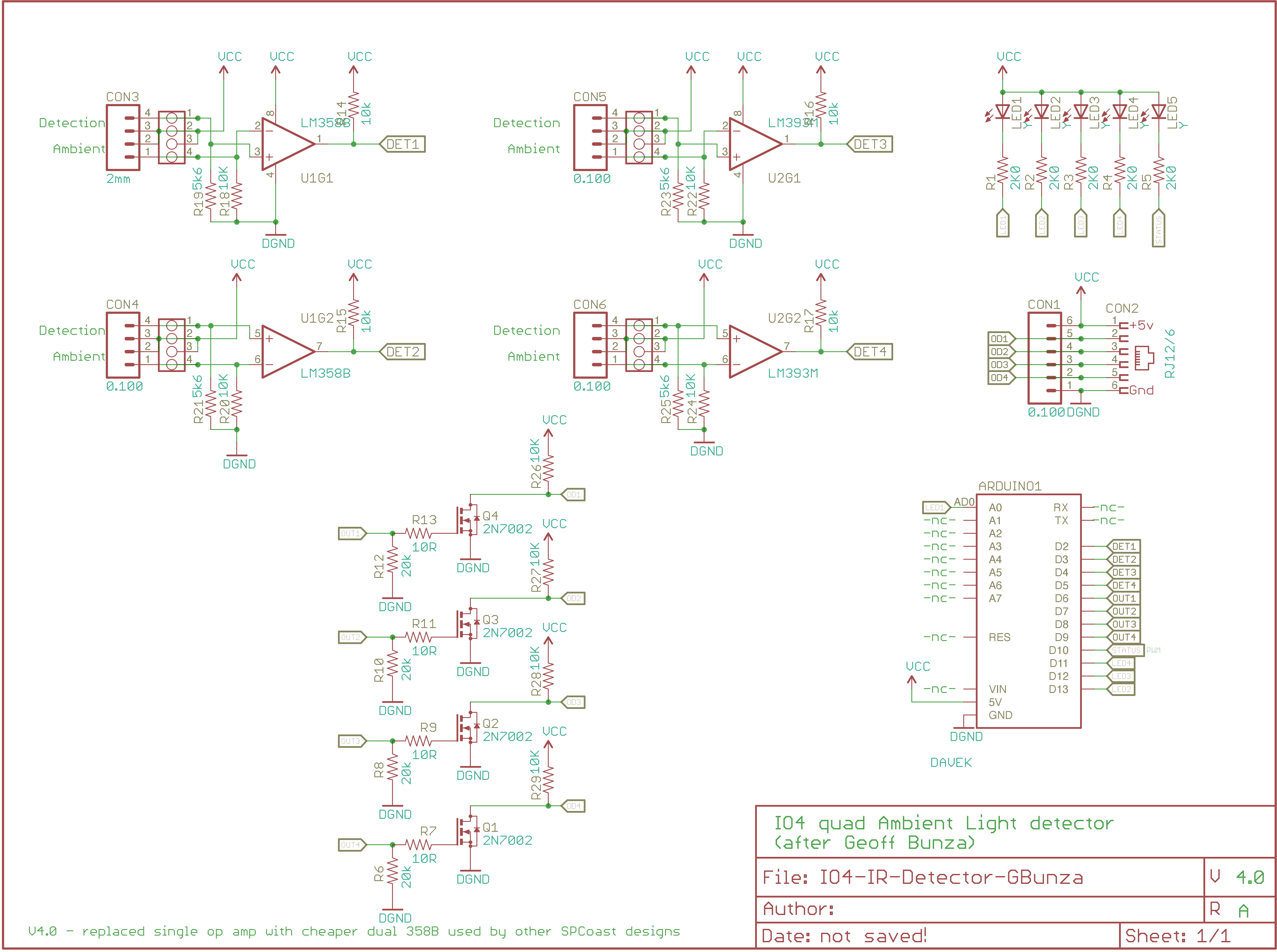
It has 4 independent optical detectors for high density applications. 4 Circuit Enhanced Optical Position Detector uses an Arduino ProMini (included) for its timing and de-bounce, so these parameters can be changed in software.
The output is an open drain (2N7002) which can sink up to 115mA @ up to 48V.
This design uses Geoff’s self-calibrating detection circuit, so you don’t need to adjust for ambient light level. Note the circuit won’t work in the dark unless you provide an infrared illumination source. The supply voltage range is 5 volts and the the output is an open drain (2N7002) which can sink up to 100mA @ 48V.
Geoff says:
“Every so often one needs an absolute position detector, rather than a block detector. The best I’ve used employ their own light source, but older designs use Cadmium Sulphide (CdS) photocells and depend on ambient light in the room. Both have driven me crazy with their limitations. This article describes a new design, using ambient light “seen” by the detector in two places – typically between the rails and just to the side of the track. When it notices the track light level fall below the level of the second sensor, it “indicates” the presence of an obstruction (car or loco). The beauty of this “differential” measurement is that it operates over a very wide range of light levels, does not require “aiming” to a target, needs no adjustments, and can be virtually buried in ground covering materials.”
|
|
Download IRDetector-Gbunza.ino - Arduino Sketch
Download PT19-21C-L41-TR8-Phototransistor.pdf - Documentation
Download tl331-Comparator.pdf - Documentation
IO4-IR-Detector-GBunza Version 4.0
First built: 2018-02
Derived from Geoff Bunza’s SMA Detector, published in his column in MRH as “SMA23 – A New DCC & DC Car & Loco Detector – Differential Absolute Position Detector (DAPD)” This version eschews “small” in favor of a remote mountable IO4 baseboard that can be mounted near the point of use, and then use sensors disguised as ties for the sensor electronics themselves.
It has 4 independent optical detectors for high density applications. 4 Circuit Enhanced Optical Position Detector uses an Arduino ProMini (included) for its timing and de-bounce, so these parameters can be changed in software.
The output is an open drain (2N7002) which can sink up to 115mA @ up to 48V.
This design uses Geoff’s self-calibrating detection circuit, so you don’t need to adjust for ambient light level. Note the circuit won’t work in the dark unless you provide an infrared illumination source. The supply voltage range is 5 volts and the the output is an open drain (2N7002) which can sink up to 100mA @ 48V.
Geoff says:
“Every so often one needs an absolute position detector, rather than a block detector. The best I’ve used employ their own light source, but older designs use Cadmium Sulphide (CdS) photocells and depend on ambient light in the room. Both have driven me crazy with their limitations. This article describes a new design, using ambient light “seen” by the detector in two places – typically between the rails and just to the side of the track. When it notices the track light level fall below the level of the second sensor, it “indicates” the presence of an obstruction (car or loco). The beauty of this “differential” measurement is that it operates over a very wide range of light levels, does not require “aiming” to a target, needs no adjustments, and can be virtually buried in ground covering materials.”
|
|
|
UNPUBLISHED
IO4-IR-Detector-GBunza Version 3.2
First built: 2018-02
Derived from Geoff Bunza’s SMA Detector, published in his column in MRH as “SMA23 – A New DCC & DC Car & Loco Detector – Differential Absolute Position Detector (DAPD)” This version eschews “small” in favor of a remote mountable IO4 baseboard that can be mounted near the point of use, and then use sensors disguised as ties for the sensor electronics themselves.
It has 4 independent optical detectors for high density applications. 4 Circuit Enhanced Optical Position Detector uses an Arduino ProMini (included) for its timing and de-bounce, so these parameters can be changed in software.
The output is an open drain (2N7002) which can sink up to 115mA @ up to 48V.
This design uses Geoff’s self-calibrating detection circuit, so you don’t need to adjust for ambient light level. Note the circuit won’t work in the dark unless you provide an infrared illumination source. The supply voltage range is 5 volts and the the output is an open drain (2N7002) which can sink up to 100mA @ 48V.
Geoff says:
“Every so often one needs an absolute position detector, rather than a block detector. The best I’ve used employ their own light source, but older designs use Cadmium Sulphide (CdS) photocells and depend on ambient light in the room. Both have driven me crazy with their limitations. This article describes a new design, using ambient light “seen” by the detector in two places – typically between the rails and just to the side of the track. When it notices the track light level fall below the level of the second sensor, it “indicates” the presence of an obstruction (car or loco). The beauty of this “differential” measurement is that it operates over a very wide range of light levels, does not require “aiming” to a target, needs no adjustments, and can be virtually buried in ground covering materials.”
|
|
|
UNPUBLISHED
IRDetector-Gbunza.ino
//
//  IR Detector
//
//  Circuit: See the IO4-IR-Detector-GBunza board on SPCoast.com
//

#include <Wire.h>
#include <elapsedMillis.h>

//#define USE_LCD
#define DEBUG
#define HYSTERESIS 2000    // in mS units, 2000 = 2.0 seconds
#define OCCUPIED LOW
#define EMPTY    ~OCCUPIED

#ifdef USE_LCD
#define I2C_ADDR    0x27

#include <LiquidCrystal_I2C.h>
LiquidCrystal_I2C  lcd(I2C_ADDR, 16,2);
elapsedMillis updateLCDWatchdog;
#endif

#define PIN_DET1                2 // pin from IR comparator
#define PIN_DET2                3 // pin from IR comparator
#define PIN_DET3                4 // pin from IR comparator
#define PIN_DET4                5 // pin from IR comparator

#define PIN_OUT1                6 // pin to feedback connector
#define PIN_OUT2                7 // pin to feedback connector
#define PIN_OUT3                8 // pin to feedback connector
#define PIN_OUT4                9 // pin to feedback connector

#define PIN_LED1                13 // pin to LED
#define PIN_LED2                12 // pin to LED
#define PIN_LED3                11 // pin to LED
#define PIN_LED4                10 // pin to LED


#define VERSION "v1.1"  // initial version, debug LEDS and basic functionality
#define DATE    "12-06-2019" //  "6-15-2017"
#define NAME    "Quad IR Detector"


class Detector {
public:
    Detector(void) {};
    void init(int number, int det, int out, int led) {
        num = number; // which detector - for debugging
        detPin = det;
        outPin = out;
        ledPin = led;

        detected = false;
	active   = false;
        delaytime = 0;
        pinMode(ledPin,  OUTPUT);	// visual Feedback
        pinMode(outPin,  OUTPUT);	// digital reporting back to computer
        pinMode(detPin,  INPUT);	// input from IR detector circuit

        digitalWrite(outPin, EMPTY);    // Leave the detection pin "off"
        digitalWrite(ledPin, EMPTY);    // Leave the LED "off"
    };

    bool  isActive()   { return active == true; }
    bool  isDetected() { return detected == true; }

    int check(void) {
        active =  digitalRead(detPin);   // read state

        if (active) {           // something has been detected...
            if (detected == false) { // newly triggered
                // Serial.print("Detector ");
                // Serial.print(num, DEC);
                // Serial.print(" now ON  ");
            }
            delaytime = 0;  // expiration timer is reset every time detection is seen
            detected = true;
        }
        if (detected) {
            if (delaytime < HYSTERESIS) {
                digitalWrite(outPin, OCCUPIED);
                digitalWrite(ledPin, OCCUPIED);
            } else {
                // Serial.print("Detector ");
                // Serial.print(num, DEC);
                // Serial.print(" now OFF ");
                digitalWrite(outPin, EMPTY);
                digitalWrite(ledPin, EMPTY);
                detected = false;
            }
        }
        return detected ? 1 : 0;
    };

private:
    int num;
    elapsedMillis delaytime;
    bool detected, active;
    int detPin;
    int outPin;
    int ledPin;
};

Detector circuit[4];

void setup() {

#ifdef USE_LCD
  lcd.init();               // initialize the lcd
  lcd.backlight();
  lcd.setCursor(0, 0); lcd.print(NAME);
  lcd.setCursor(0, 1); lcd.print(DATE); lcd.print(VERSION);
  updateLCDWatchdog = 0;
#endif

  circuit[0].init(1,PIN_DET1, PIN_OUT1, PIN_LED1);
  circuit[1].init(2,PIN_DET2, PIN_OUT2, PIN_LED2);
  circuit[2].init(3,PIN_DET3, PIN_OUT3, PIN_LED3);
  circuit[3].init(4,PIN_DET4, PIN_OUT4, PIN_LED4);

  delay(1000);

#ifdef USE_LCD
  lcd.clear();
#endif
}

void loop() {
    for (int x = 0; x < 4; x++) {
        circuit[x].check();
    }
#ifdef USE_LCD
    if (updateLCDWatchdog > 100) {
        updateLCDWatchdog = 0;

    lcd.setCursor(0, 0);
    lcd.print("T1: "); lcd.print(circuit[0].isActive() ? "A" : " ");  lcd.print(circuit[0].isDetected() ? "D" : " ");
    lcd.print("T2: "); lcd.print(circuit[1].isActive() ? "A" : " ");  lcd.print(circuit[1].isDetected() ? "D" : " ");
    lcd.setCursor(0, 1);
    lcd.print("T3: "); lcd.print(circuit[2].isActive() ? "A" : " ");  lcd.print(circuit[2].isDetected() ? "D" : " ");
    lcd.print("T4: "); lcd.print(circuit[3].isActive() ? "A" : " ");  lcd.print(circuit[3].isDetected() ? "D" : " ");
    }
#else
    delay(10);
#endif
}
This technical documentation is licensed under the CERN Open Hardware Licence v1.2