PCRdemo2015
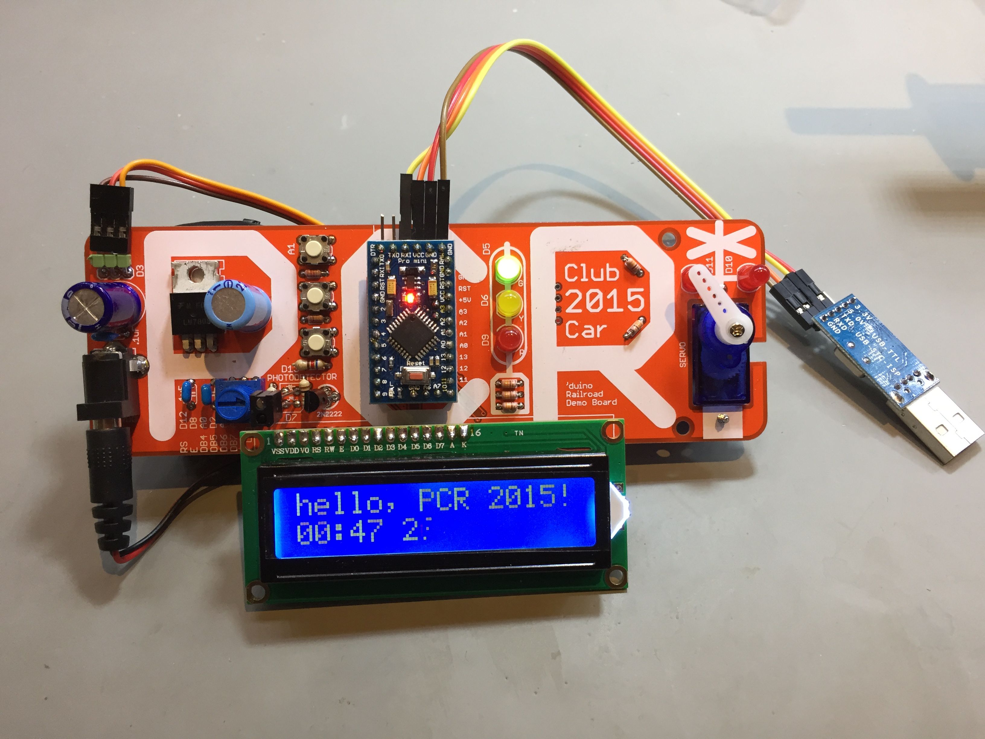
Demo code for PRC1025 demo board
|
Download PCRdemo2015.ino - Arduino Sketch
PCRdemo2015
/*
 *    Demo code for PRC1025 demo board
 *
 *    Includes LEDs (R/R for Xing, RYG for a signal), pushbuttons,
 *    a servo and an LCD.
 *
 *    The demo uses the buttons to raise and lower the crossing gate and
 *    turn on/off the blinking crossing lights.
 *
 *    The demo also runs timed activities "in the background", so that the
 *    signal changes aspects and the crossing automatically triggers every
 *    once in a while.
 *
 *    The board also includes provisions for an IR sensor - unfortunately,
 *    the circuit was miswired to a digital pin instead of an analog one, so
 *    it doesn't (and can't) work without board trace rerouting.  Oops.
 */
#include <LiquidCrystal.h>
#include <elapsedMillis.h>
#include <Servo.h>

#define MOD1

/*
 * The circuit:
 * LCD
 *     D8  Enable pin
 *     nc  D0 pin
 *     nc  D1 pin
 *     nc  D2 pin
 *     nc  D3 pin
 *     A0  D4 pin
 *     D2  D5 pin
 *     A2  D6 pin
 *     A3  D7 pin
 *     GND R/W pin
 *     GND VSS pin
 *     +5v VCC pin
 *     10K resistor:
 *       ends to +5V and ground
 *       wiper to LCD VO pin (pin 3)
 *
 * A1   Voltage divider ladder with momentary pushbuttons
 *      (Voltage at pin determines which button was pressed, if any)
 *
 * "signal head" - D5 PWM green
 *               - D6 PWM yellow
 *               - D9 PWM red
 * "crossbucks"  - D10 PWM red LEDs
 *               - D11 PWM red LEDs
 *
 * Pin assignments:
 * ================
 * D0   TTL/USB serial RX
 * D1   TTL/USB serial TX
 * D2   LCD high nibble data5
 * D3   PWM Servo
 * D4   unused
 * D5   "signal head" - PWM green
 * D6                 - PWM yellow
 * D7   unused
 * D8   LCD "E"nable
 * D9                 - PWM red
 * D10  "crossbucks"  - PWM red LEDs
 * D11  "crossbucks"  - PWM red LEDs
 * D12  unused
 * D13  unused (onboard LED...)
 *
 * A0   LCD high nibble data4
 * A1   pushbuttons
 * A2   LCD high nibble data6
 * A3   LCD high nibble data7
 * A4   I2C SDA
 * A5   I2C SCL
 * A6   unused - analog input only (no output capability)
 * A7   unused - analog input only (no output capability)
 */

// pushbuttons...
#define PBUTTONS     1  // A1

// "crossbucks" - red LEDs
#define REDX1 10
#define REDX2 11

// "signal head"
#define RSIG  9
#define YSIG  6
#define GSIG  5
// Finally, the servo control pin
#define SERVO 3

// -----------------------------------------
// change these to match what you want
// -----------------------------------------

#define GATE_UP     95
#define GATE_DOWN  150
#define GREETING "Hello, Larry"

#define SECONDS (unsigned long)1000
#define MINUTES (unsigned long)(60 * SECONDS)

#define CROSSING_FREQUENCY  ((unsigned long)( 5 * MINUTES))
#define CROSSING_PREFLASH   ((unsigned long)( 4 * SECONDS))
#define CROSSING_GATEDOWN   ((unsigned long)(10 * SECONDS))
#define CROSSING_POSTFLASH  ((unsigned long)( 3 * SECONDS))

// -----------------------------------------


#ifdef MOD1 // John's modified prototype board
LiquidCrystal lcd(12, 8, 7, 2, A2, A3);
#else
LiquidCrystal lcd(12, 8, A0, 2, A2, A3);
#endif
Servo myservo;  // create servo object to control a servo

// elapsedMillis variables are "magic C++" - they actually reflect the elapsed
// time since they were last time they were set.  The design pattern is to set
// them to 0 when you want to start a timed activity, and then check to see if
// it reaches the desired timeout value...
elapsedMillis   clockAnimationTime,
		flashertime,
		blinktime,
		signalAnimationTime,
		crossingAnimationTime;

boolean isXingOn, xingblinker = 0, sigblinker=0;
int sigstate = 0;
int crossingstate = 0;
int lastButton;

#define OFF   0x0FF
#define ON    0x000
#define BLINK 0x1FF

// global variables that hold the current values of the various LEDs
int r, g, y, x1, x2;
// and if fading is used, the target vvalues as well...
int target_r, target_g, target_y, target_x1, target_x2;

// Read resitive voltage divider to determine which button was pressed
// input:  analog pin to read
// output: button pressed, if any:
#define BUTTON_3     2
#define BUTTON_2     1
#define BUTTON_1     0
#define BUTTON_NONE  -1

int getButton(int p) {
    int ButtonVoltage = analogRead(p);
    // Observed analogRead() returned values:
    //     NONE:    1023
    //     B3:       310
    //     B2:       131
    //     B1:         0
    // logic below is liberal in setting boundries between buttons to account for resistor tolerances

    if (ButtonVoltage > 500) return BUTTON_NONE;    // No button pressed should be 1023
    if (ButtonVoltage > 250) return BUTTON_3;
    if (ButtonVoltage > 100) return BUTTON_2;
    return BUTTON_1;
}


int setLED(int p, int target, int current) {
      int desired = target & 0x0FF;
      if (desired == current) {
          return desired;
      } else {
          int newvalue = desired;
          if (p < 9 || p > 11) {  // showing off fade -vs- no fade - don't fade the RED LEDs
          if (desired > current) { newvalue = min(current + 1, desired); }
          if (desired < current) { newvalue = max(current - 1, desired); }
          }
          analogWrite(p,  newvalue);
          return newvalue;
      }
}

void setup() {
    // setup code, run once:

    pinMode(SERVO,    OUTPUT);  // servo
    pinMode(GSIG,     OUTPUT);  // G LED
    pinMode(YSIG,     OUTPUT);  // Y LED
    pinMode(RSIG,     OUTPUT);  // R LED
    pinMode(REDX1,    OUTPUT);  // L Xing R LED
    pinMode(REDX2,    OUTPUT);  // R Xing R LED
    pinMode(PBUTTONS, INPUT);   // pushbuttons
    pinMode(4,        OUTPUT);   // pushbuttons

    myservo.attach(SERVO);
    myservo.write(GATE_UP);

    lcd.begin(16, 2);
    lcd.print(GREETING);
    lcd.setCursor(0, 1);
    lcd.print("PCR '15");

    signalAnimationTime  = (10 * SECONDS);

    isXingOn = false;
    r = y = g = x1 = x2 = ON;
    target_r = target_y = target_g = target_x1 = target_x2 = OFF;

    x1 = setLED(REDX1, target_x1, x1);
    x2 = setLED(REDX2, target_x2, x2);
    r  = setLED(RSIG,  target_r,  r);
    y  = setLED(YSIG,  target_y,  y);
    g  = setLED(GSIG,  target_g,  g);

    lastButton = BUTTON_NONE;
}

void loop() {
    // any buttons pressed?
    int button1 = getButton(PBUTTONS);
    delay(1);  //  debounce (if values differ, we are in the middle of a press
               //  or release, and will ignore the buttons this pass)
    int button2 = getButton(PBUTTONS);

    if ((button1 == button2) && (button1 != lastButton)) {
        // solid button press, first time seen...
        // choose what to do
        switch (button1) {
             case BUTTON_1:
                            myservo.write(GATE_UP);
                            break;

            case BUTTON_2:
                            isXingOn = !isXingOn; // turn crossing on & off...
                            if (isXingOn) {
                                target_x1 = BLINK;
                                target_x2 = BLINK;
                            } else {
                                target_x1 = OFF;
                                target_x2 = OFF;
                            }
                            flashertime = 0;
                            break;
             case BUTTON_3:
                            myservo.write(GATE_DOWN);
                            break;
             default:
             case BUTTON_NONE:
                            // do nothing
                            break;
        }
        // remember the last button pressed to prevent multiple invocations
        // (stuttering, repeat...) of a single press
        lastButton = button1;
    }

    // have the signals blink at a slightly different rate than the crossing flashers,
    // just to show that it can be done.

    if (flashertime > 800) {
        flashertime = 0;
        xingblinker = ! xingblinker;
    }
    if (blinktime > 750) {
        blinktime = 0;
        sigblinker = ! sigblinker;
    }

    // Each animation we're controlling has its own timer that we can check to
    // see if it is time to do work...  for example, we can display a crude
    // clock on the LCD by incrementing a counter every second:

    if (clockAnimationTime > (1 * SECONDS)) {    // trigger every second...
        unsigned long h, m, s;
        clockAnimationTime = 0;
        // set the cursor to LCD column 8, line 1
        // (note: line 1 is the second row, since counting begins with 0):
        lcd.setCursor(8, 1);
        // print the time since reset:
        // simple formatting to simulate hours, minutes and seconds
        s = millis() / SECONDS;
        h = (s / (60*60)) % 24;
        m = (s / (60))    % 60;
        s = s             % 60;
        lcd.print(h >= 10 ? "" : " " );lcd.print(h, DEC); lcd.print(':');
        lcd.print(m >= 10 ? "" : "0" );lcd.print(m, DEC); lcd.print(':');
        lcd.print(s >= 10 ? "" : "0" );lcd.print(s, DEC);
    }

    switch (crossingstate) {
      case 0:  // waiting to trigger...
              if (crossingAnimationTime > CROSSING_FREQUENCY) {  // pretend
                  crossingAnimationTime = 0;                       // train is
                  crossingstate = 1;                               // coming...
                  isXingOn = true;    // start flashing
                  target_x1 = BLINK;
                  target_x2 = BLINK;
              }
              break;
      case 1: // gates down
              if (crossingAnimationTime > CROSSING_PREFLASH) {
                  crossingAnimationTime = 0;
                  crossingstate = 2;
                  myservo.write(GATE_DOWN);
              }
              break;
      case 2:  // gates back up
              if (crossingAnimationTime > CROSSING_GATEDOWN) {
                  crossingAnimationTime = 0;
                  crossingstate = 3;
                  myservo.write(GATE_UP);
              }
              break;
      case 3:  // done flashing, go back to waiting...
              if (crossingAnimationTime > CROSSING_POSTFLASH) {
                  crossingAnimationTime = 0;
                  isXingOn = false;
                  target_x1 = OFF;
                  target_x2 = OFF;
                  crossingstate = 0;
              }
              break;

    }

    if (signalAnimationTime > (10 * SECONDS)) {  // walk thru the signal aspects
        signalAnimationTime = 0;
        switch (sigstate) {
          case 0: target_r=BLINK; target_y=BLINK; target_g=BLINK; sigstate = 1; break;  // TEST mode - flash all LEDs
          case 1: target_r=ON;    target_y=OFF;   target_g=OFF;   sigstate = 2; break;  // STOP
          case 2: target_r=BLINK; target_y=OFF;   target_g=OFF;   sigstate = 3; break;  // RESTRICTING
          case 3: target_r=OFF;   target_y=ON;    target_g=OFF;   sigstate = 4; break;  // APPROACH
          case 4: target_r=OFF;   target_y=BLINK; target_g=OFF;   sigstate = 5; break;  // ADVANCE APPROACH
          case 5: target_r=OFF;   target_y=OFF;   target_g=ON;    sigstate = 1; break;  // CLEAR
        }
    }

    // actually control the LEDs
    x1 = setLED(REDX1,target_x1 == BLINK ? (xingblinker ? ON : OFF) : target_x1, x1);
    x2 = setLED(REDX2,target_x2 == BLINK ? (xingblinker ? OFF: ON)  : target_x2, x2);
    r  = setLED(RSIG, target_r  == BLINK ? (sigblinker  ? ON : OFF) : target_r,  r);
    y  = setLED(YSIG, target_y  == BLINK ? (sigblinker  ? ON : OFF) : target_y,  y);
    g  = setLED(GSIG, target_g  == BLINK ? (sigblinker  ? ON : OFF) : target_g,  g);

}
This sketch is licensed under the MIT License