IO4-SignalDriver
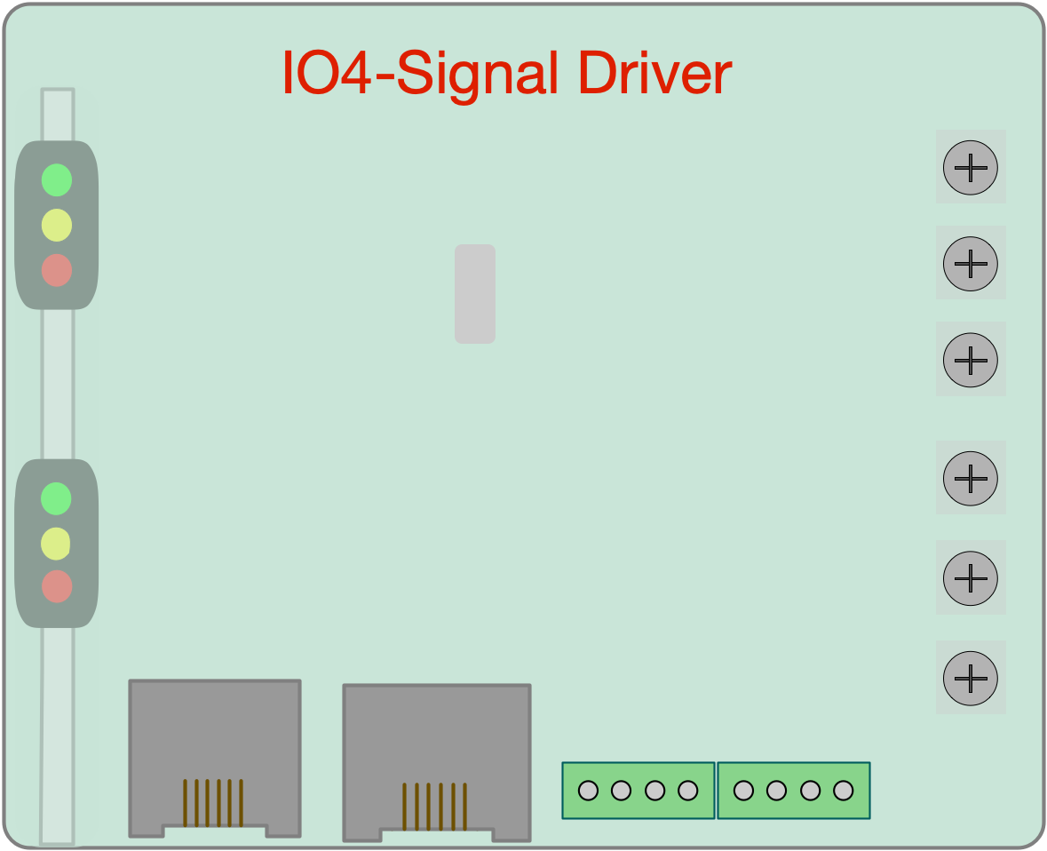
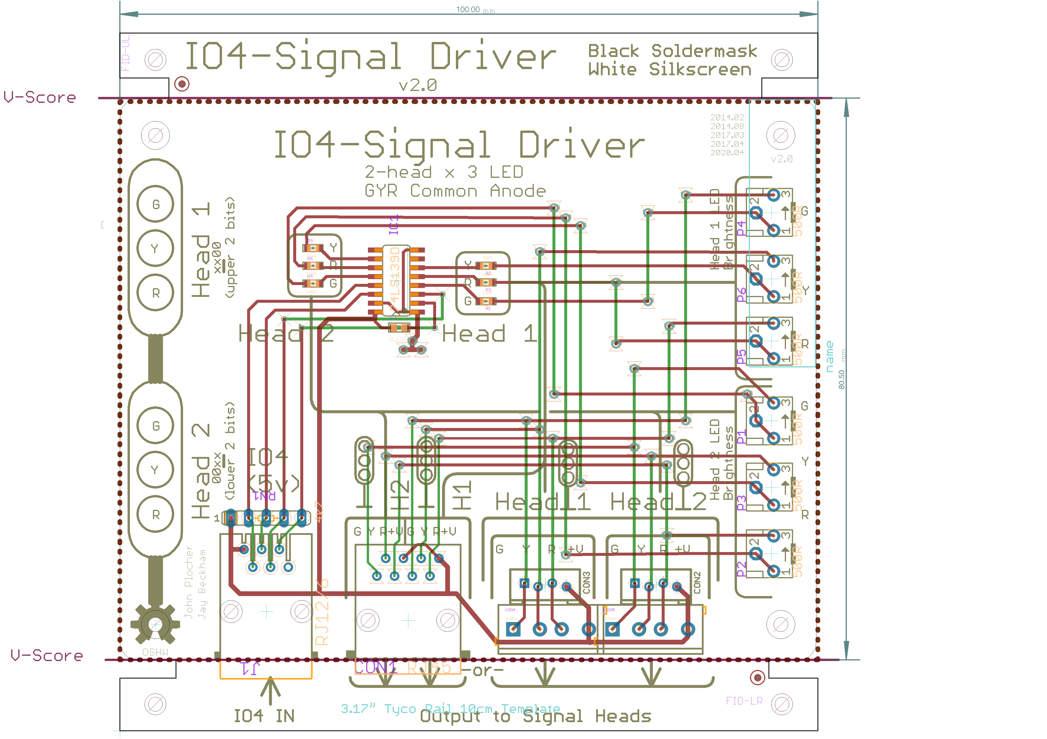
IO4 Output adapter driver for a 2-head signal mast
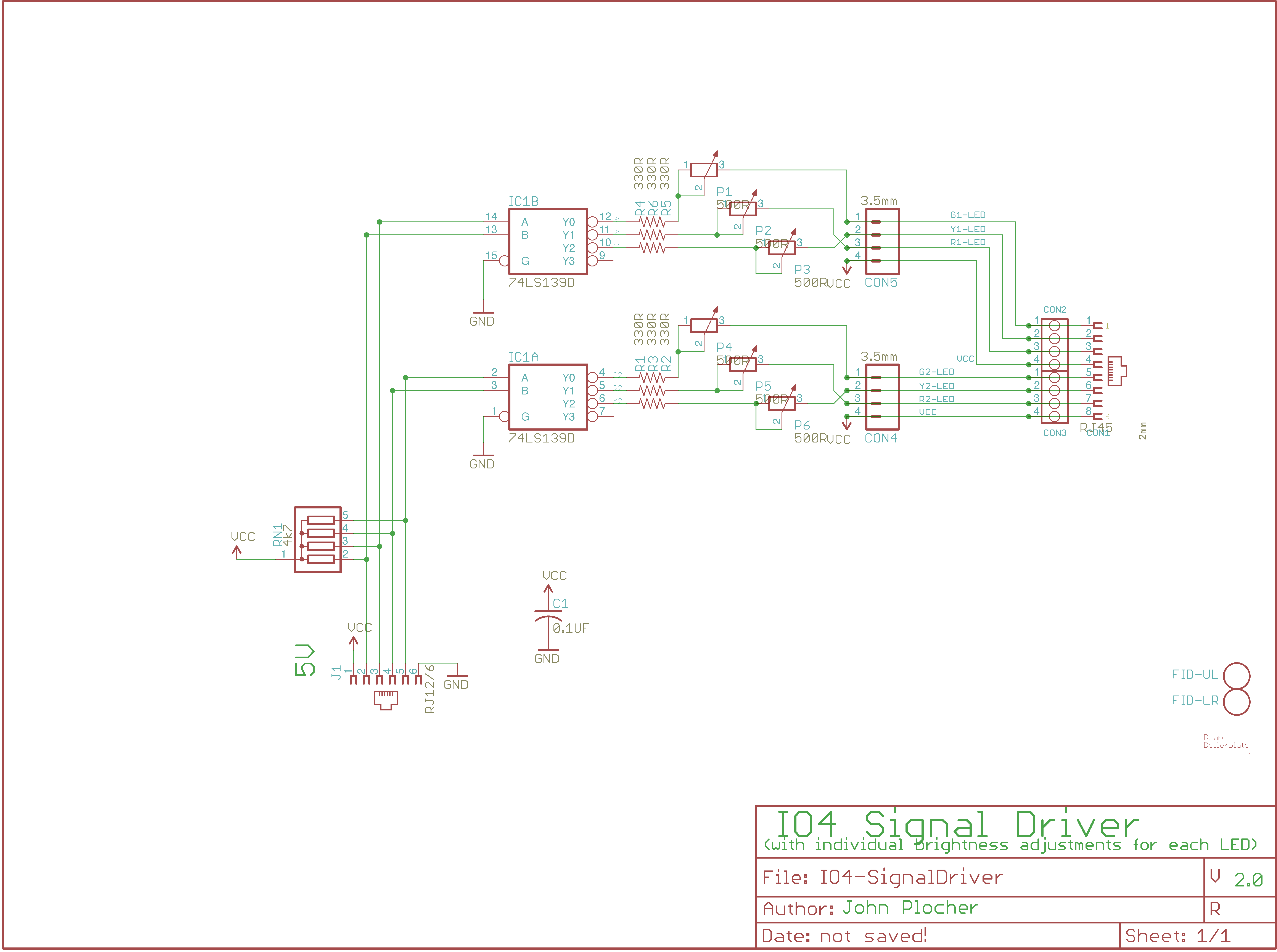
Takes an IO4-Output and drives 2x 3-LED common Anode signal heads using a demultiplexor logic chip. Designed in conjunction with Jay Beckham for his South Shore Lines layout Circuit testing:
- The board needs to share a common ground with the remote controller (CMRI SMINI…) as the RJ45 only carries control signals
- Drive the board with 5V DC through the IO4 connection
- Signal heads / LEDs are “common anode” - pin4 of the signal head connector is VCC, the “colors” pins are driven LOW to energize the LED.
- All control lines are pulled up logically on the signal driver board.
- The board can drive 2x signal heads, each with R, Y, G and DARK aspects
-
- Control signals 1 & 2 and 3 & 4, each control one head:
- 00 - Green
- 01 - Yellow
- 10 - Red
- 11 - Dark
-
- The discrete resistors set a safe limit on the current allowed to the LED, and the trimmer pots can be used to further adjust the brightness.
- The exact value depends on the specific attributes of the LED variety being used - specifically the forward voltage drop across the device. This info is found in the data sheet for the LED in question, or can be found experimentally.
- Example: with a 5v supply and a LED that drops 2.2v, the resistor sees (5-2.2 = 2.8v). If we wish to limit the max current to 15mA, we need a fixed resistor of (2.8v / 0.015 = ~180 ohms). If we add a 500 ohn trimmer resistor, that lets us adjust the current from 15mA max to about 4mA min. High efficiency LEDs might need even LESS current, so upping the fixed resistor to 470R or even 1K0 might be appropriate.
|
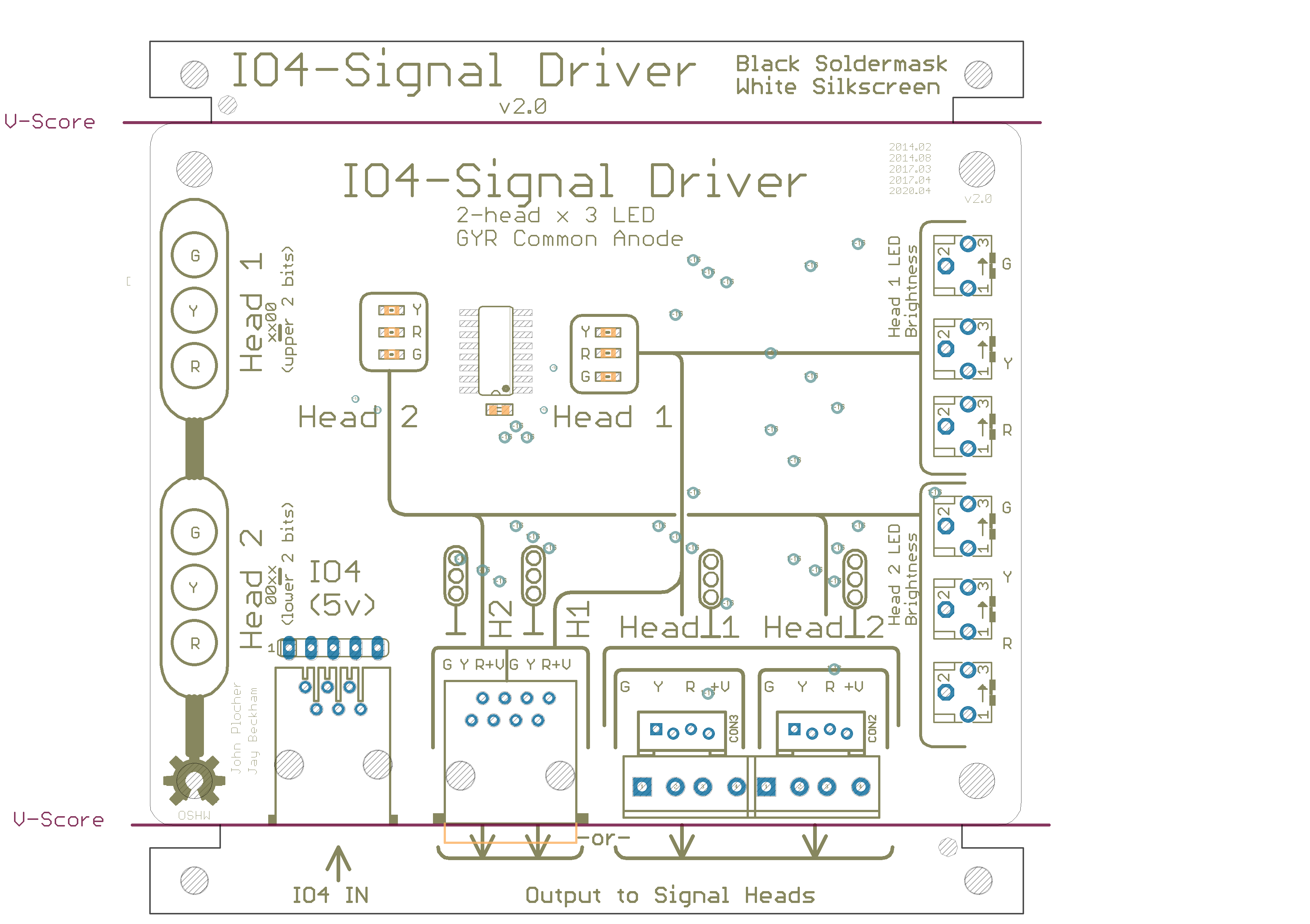
IO4-SignalDriver Version 2.0
Not built
Takes an IO4-Output and drives 2x 3-LED common Anode signal heads using a demultiplexor logic chip. Designed in conjunction with Jay Beckham for his South Shore Lines layout Circuit testing:
- The board needs to share a common ground with the remote controller (CMRI SMINI…) as the RJ45 only carries control signals
- Drive the board with 5V DC through the IO4 connection
- Signal heads / LEDs are “common anode” - pin4 of the signal head connector is VCC, the “colors” pins are driven LOW to energize the LED.
- All control lines are pulled up logically on the signal driver board.
- The board can drive 2x signal heads, each with R, Y, G and DARK aspects
-
- Control signals 1 & 2 and 3 & 4, each control one head:
- 00 - Green
- 01 - Yellow
- 10 - Red
- 11 - Dark
-
- The discrete resistors set a safe limit on the current allowed to the LED, and the trimmer pots can be used to further adjust the brightness.
- The exact value depends on the specific attributes of the LED variety being used - specifically the forward voltage drop across the device. This info is found in the data sheet for the LED in question, or can be found experimentally.
- Example: with a 5v supply and a LED that drops 2.2v, the resistor sees (5-2.2 = 2.8v). If we wish to limit the max current to 15mA, we need a fixed resistor of (2.8v / 0.015 = ~180 ohms). If we add a 500 ohn trimmer resistor, that lets us adjust the current from 15mA max to about 4mA min. High efficiency LEDs might need even LESS current, so upping the fixed resistor to 470R or even 1K0 might be appropriate.
|
|
|
UNPUBLISHED
This technical documentation is licensed under the CERN Open Hardware Licence v1.2