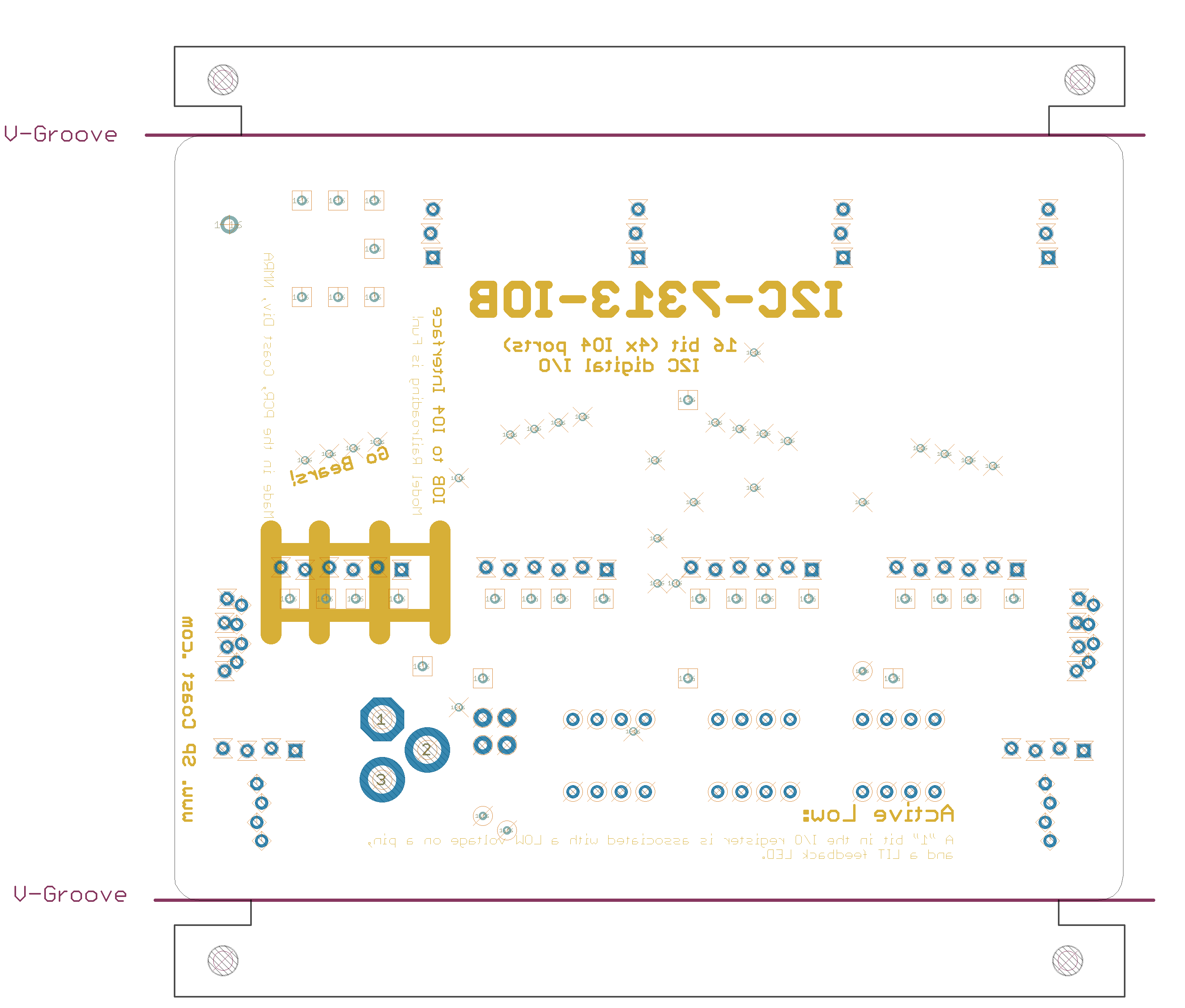
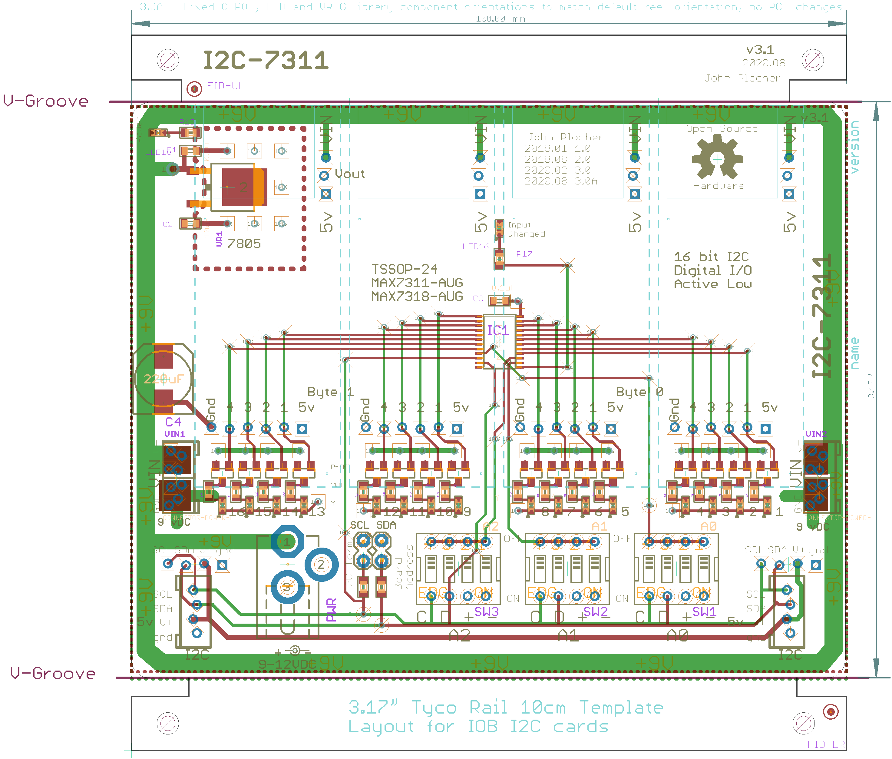
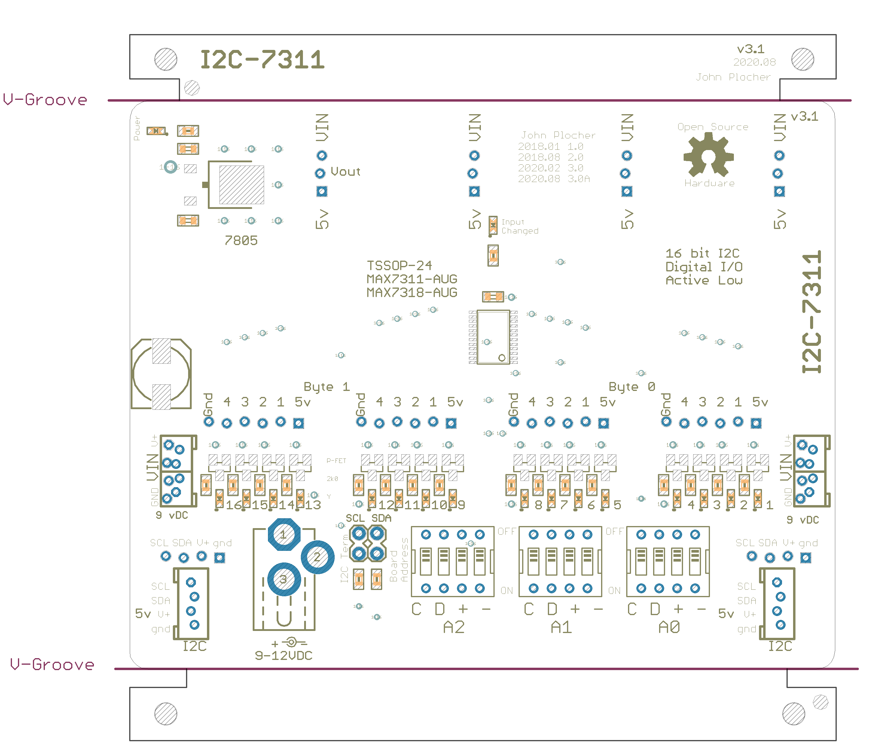
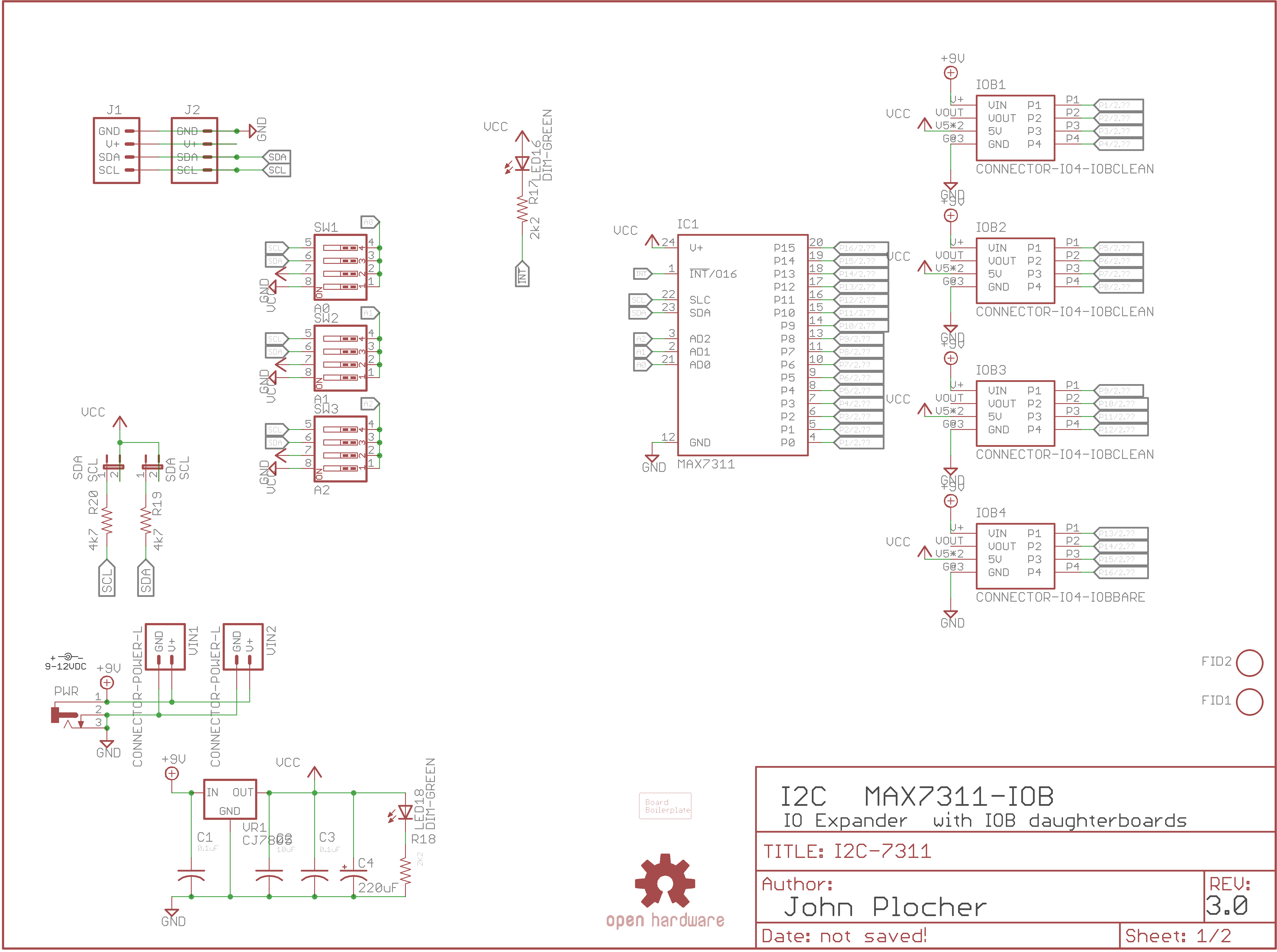
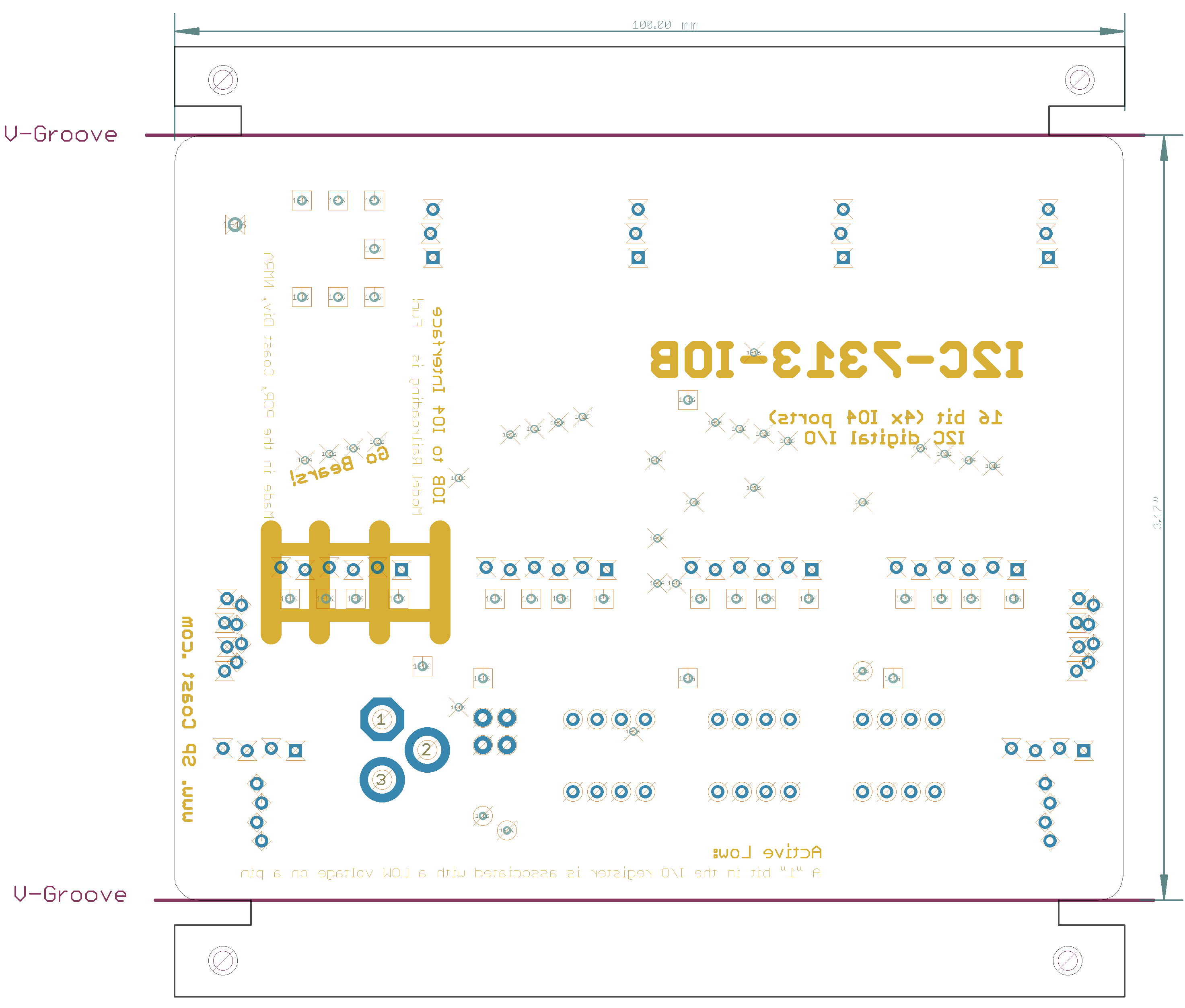
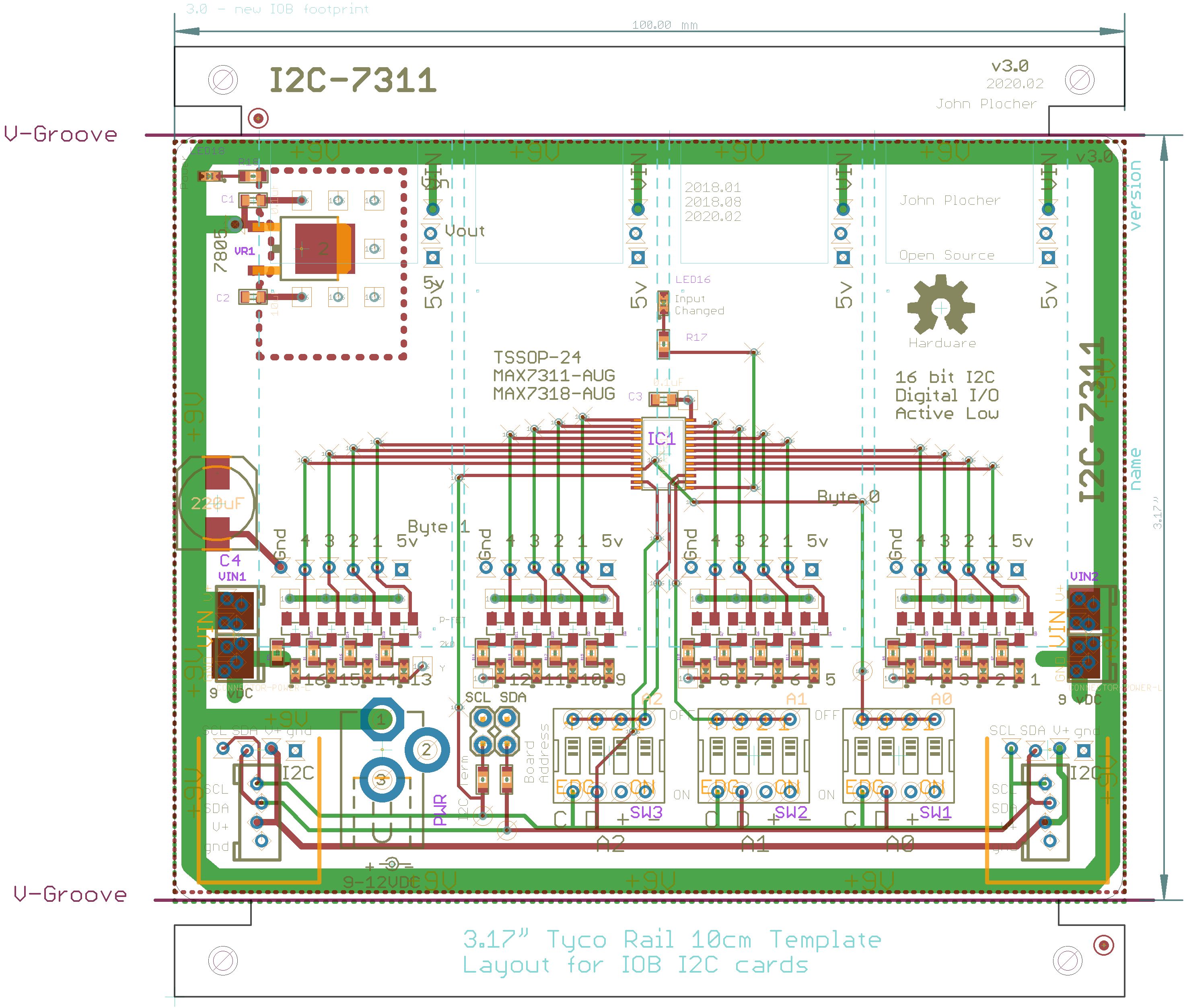
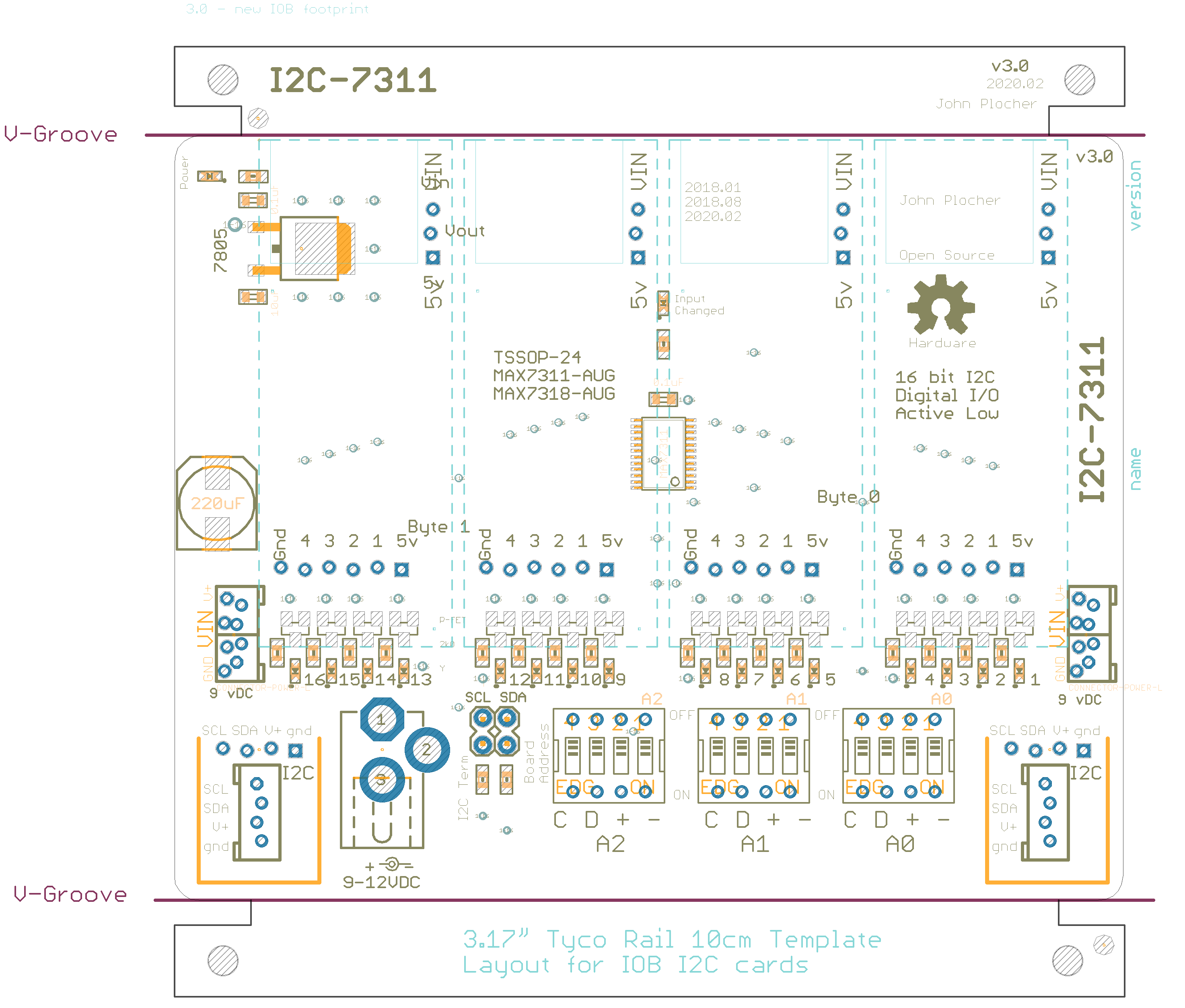
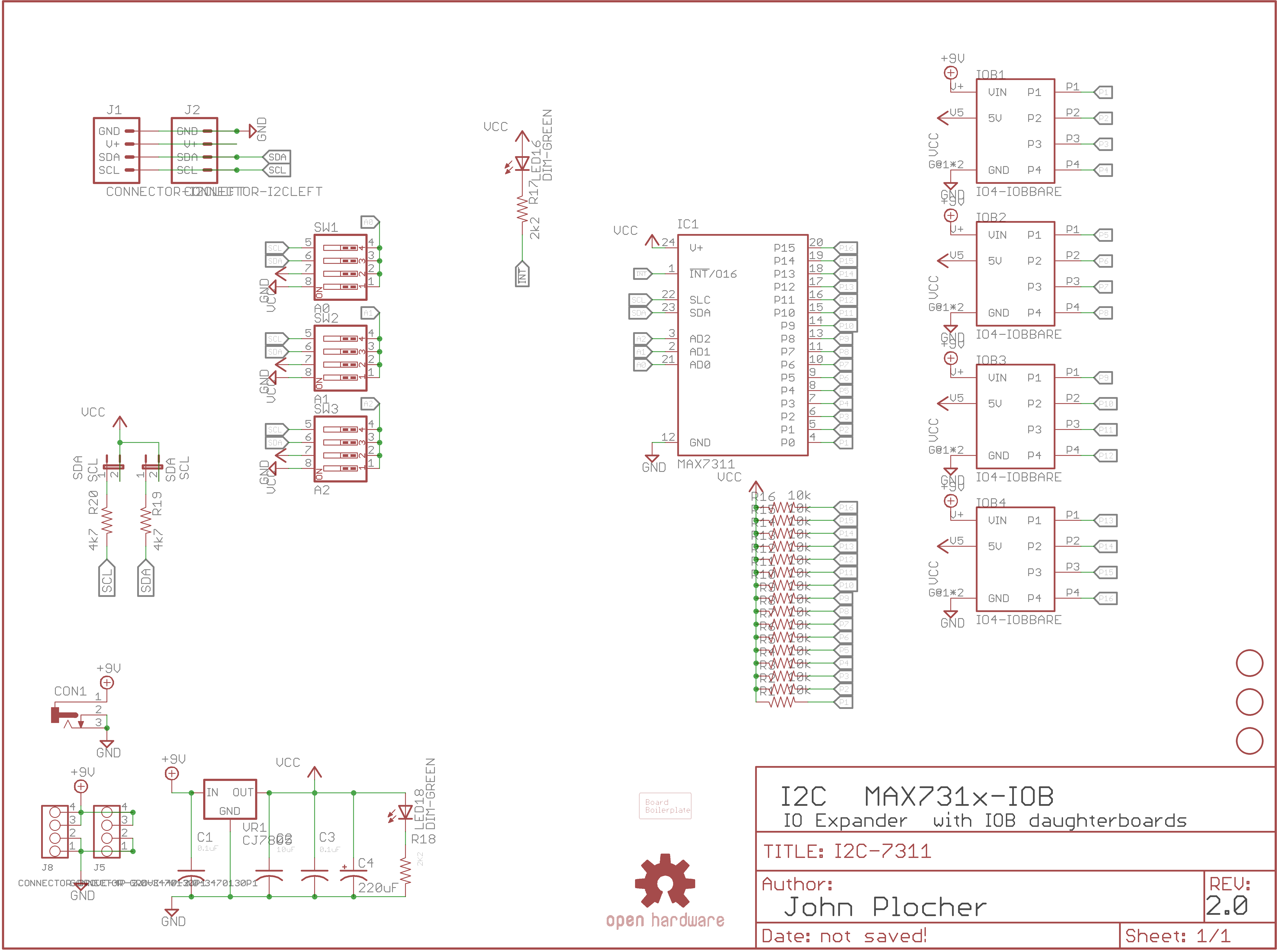
I2C-7311
I2C MAX7311/7312-based IO Expander with 4x IOB daughterboard connections
Versions:
- 1.0 - laid out for 7313 QSOP, found that the more desirable ‘11 and ‘12 chips are not available in QSOP. ‘13 is not available in SSOP.
- 2.0 - multiple silkscreen errors (still labeled as ‘13 even tho ‘11 package was used)
- 2.1 - Same as v2.0, but board has carrier for “design for fabrication” optimization. Fixed silkscreen name, change from ‘13 to ‘11
Populating with ‘11 part means no external pullups are needed, ‘12 part requires external pull ups. The board supports both variations; simply don’t populate the resistors when using the 7311.
|
|
|
Download I2C-7311.SMD-parts -
Download I2C-7311.smt550 -
Download MAX7311.pdf - Documentation
Download MAX7312.pdf - Documentation
Download MAX7313.pdf - Documentation
Download PCA9675.pdf - Documentation
Download untitled -
I2C-7311 Version 3.1
First built: 2018-08
Versions:
- 1.0 - laid out for 7313 QSOP, found that the more desirable ‘11 and ‘12 chips are not available in QSOP. ‘13 is not available in SSOP.
- 2.0 - multiple silkscreen errors (still labeled as ‘13 even tho ‘11 package was used)
- 2.1 - Same as v2.0, but board has carrier for “design for fabrication” optimization. Fixed silkscreen name, change from ‘13 to ‘11
Populating with ‘11 part means no external pullups are needed, ‘12 part requires external pull ups. The board supports both variations; simply don’t populate the resistors when using the 7311.
|
|
|
UNPUBLISHED
I2C-7311 Version 3.0
First built: 2018-08
Versions:
- 1.0 - laid out for 7313 QSOP, found that the more desirable ‘11 and ‘12 chips are not available in QSOP. ‘13 is not available in SSOP.
- 2.0 - multiple silkscreen errors (still labeled as ‘13 even tho ‘11 package was used)
- 2.1 - Same as v2.0, but board has carrier for “design for fabrication” optimization. Fixed silkscreen name, change from ‘13 to ‘11
Populating with ‘11 part means no external pullups are needed, ‘12 part requires external pull ups. The board supports both variations; simply don’t populate the resistors when using the 7311.
|
|
|
UNPUBLISHED
I2C-7311 Version 2.1
First built: 2018-08
Versions:
- 1.0 - laid out for 7313 QSOP, found that the more desirable ‘11 and ‘12 chips are not available in QSOP. ‘13 is not available in SSOP.
- 2.0 - multiple silkscreen errors (still labeled as ‘13 even tho ‘11 package was used)
- 2.1 - Same as v2.0, but board has carrier for “design for fabrication” optimization. Fixed silkscreen name, change from ‘13 to ‘11
Populating with ‘11 part means no external pullups are needed, ‘12 part requires external pull ups. The board supports both variations; simply don’t populate the resistors when using the 7311.
|
|
|
UNPUBLISHED
Documentation
Introduction
This board was originally produced to help me build control panels for my model railroad - I needed to connect many different buttons, switches and lights to an Arduino, and also connect the Arduino to a communications bus (Ethernet, CAN or Loconet), and I couldn't find anything that had both high IO point density AND visual feedback.
I started with a simple I2C based 32-pin Arduino IOShield with monitoring LEDs on each pin (Active-LOW inputs, LED is on when pin is grounded, writing a "1" to the port pulls it to ground). I was aiming to support up to the max I2C devices that can be used together, with the 8-bit board I2C-8574-IO (deprecated), that was a total of 8x boards with 128 i/o points.
The 7311 IO expanders used here will support up to 64 boards, with 1024 potential I/O points.
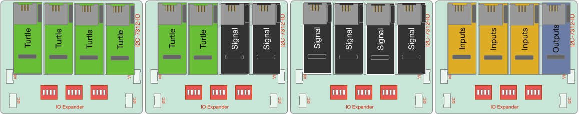
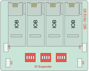
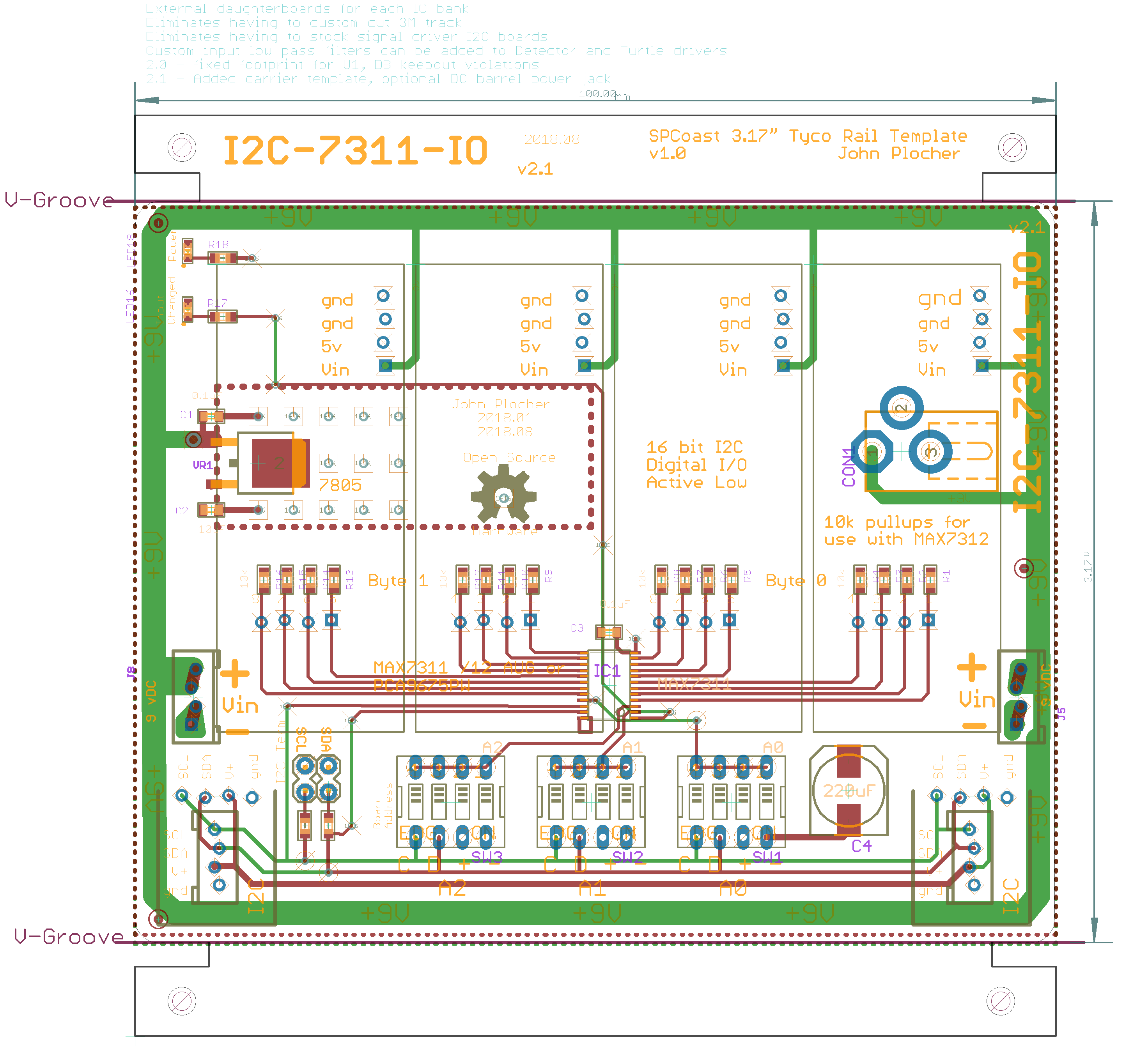
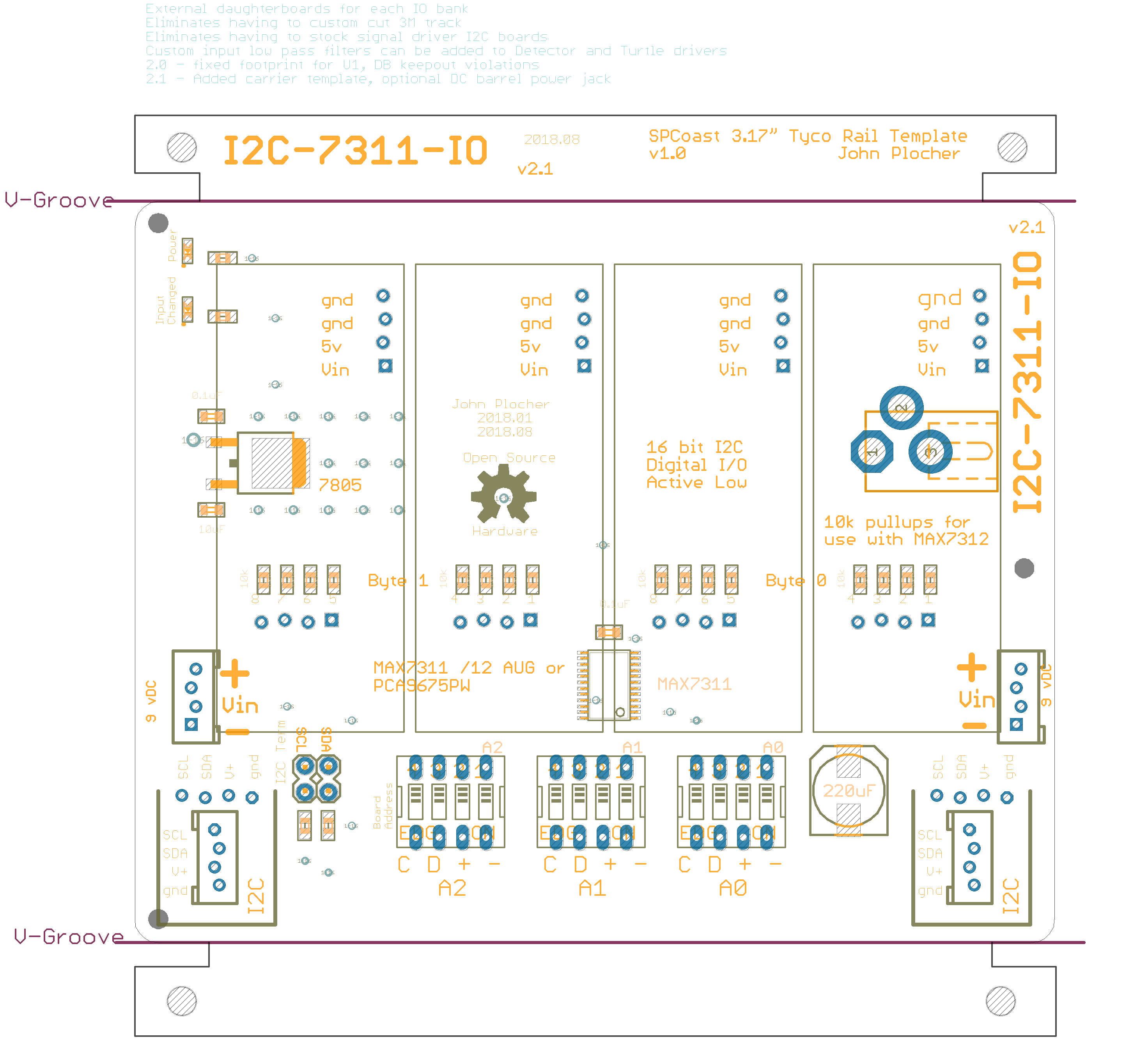
This latest design moves from overly generic and/or overly specialized designs to a generic design with daughterboards that encapsulate the appliance-specific buffering and logic. The benefits provided by these IOB boards include:
- Improved I/O bank utilization (leftover capacity is now a multiple of 4-bit daughtercard instead of 16-bit I2C card...)
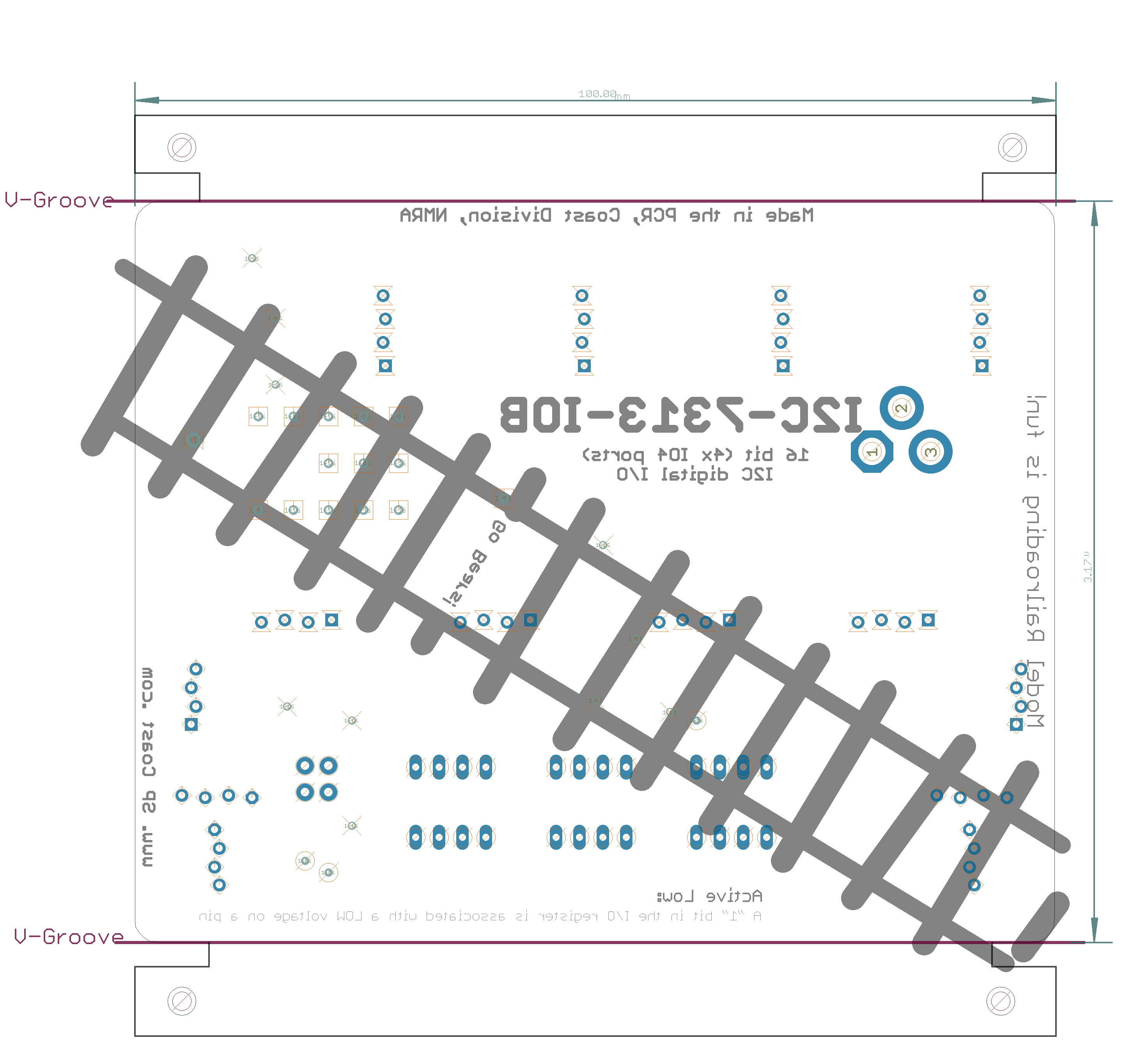
- Riser height eliminates having to custom cut 3M track
- Allows deprecation of cabling intensive signal driver IO4 and I2C boards
- Allows custom circuitry to be added to Signal, Detector and Turtle drivers
Cautions
With several hundred IO loads, and up to 256 external breakout devices, a suitable power supply (or supplies) must be used.
In practice, a 3A 9-12VDC supply a good choice for most small to medium sized control points.
This supply needs to power the core processor, its direct IO loads, the I2C expander chain AND provide ~100mA to each IO4 device. Instead of relying on the Arduino's onboard regulated supply (which is only good for about 100mA itself), each board has its own regulator with a common supply feed that can handle up to 4A @ 12v. If more power is needed, the daisy chained power feed thru can be replaced with a per-board independent supply.
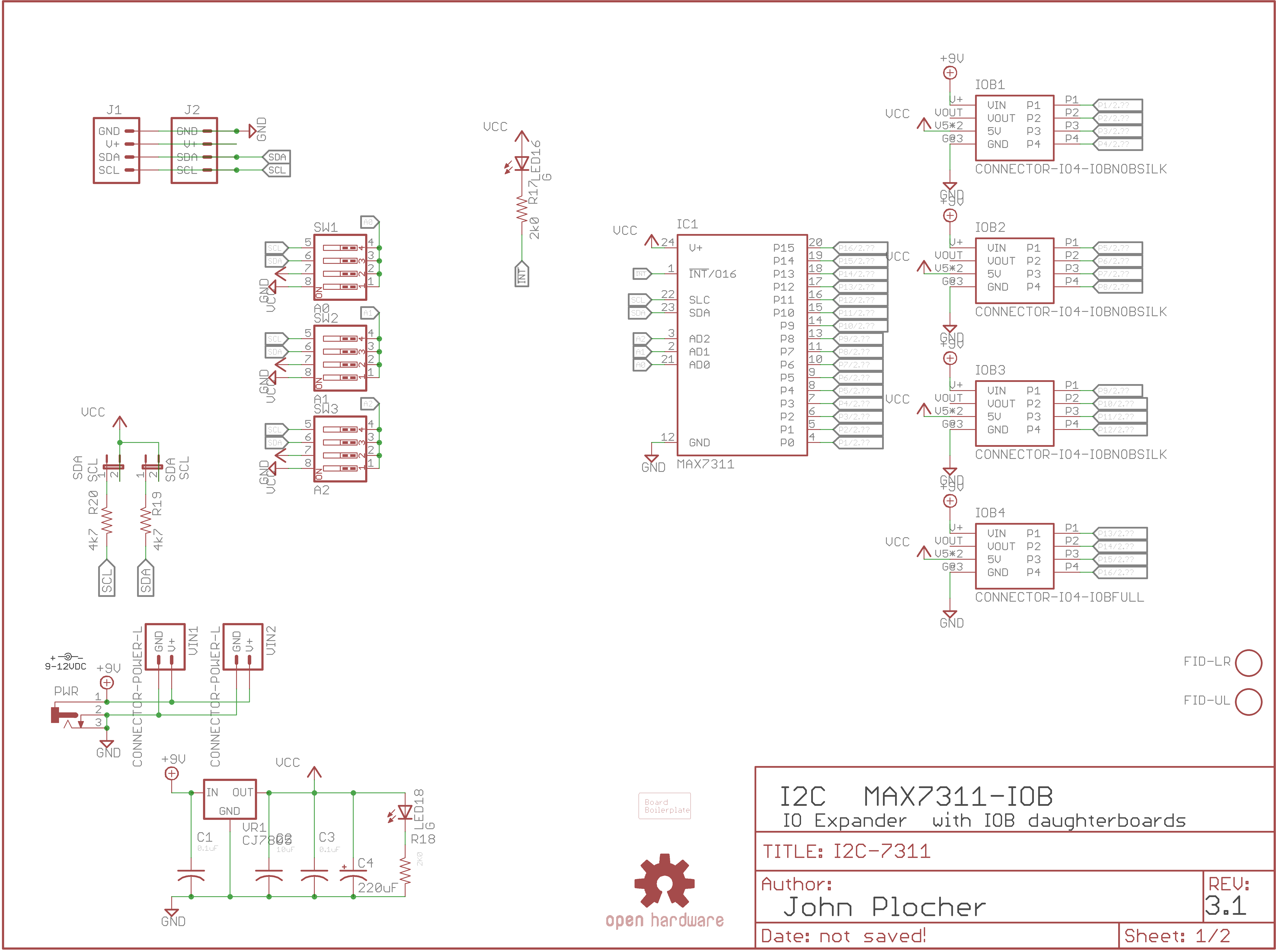
Specifications
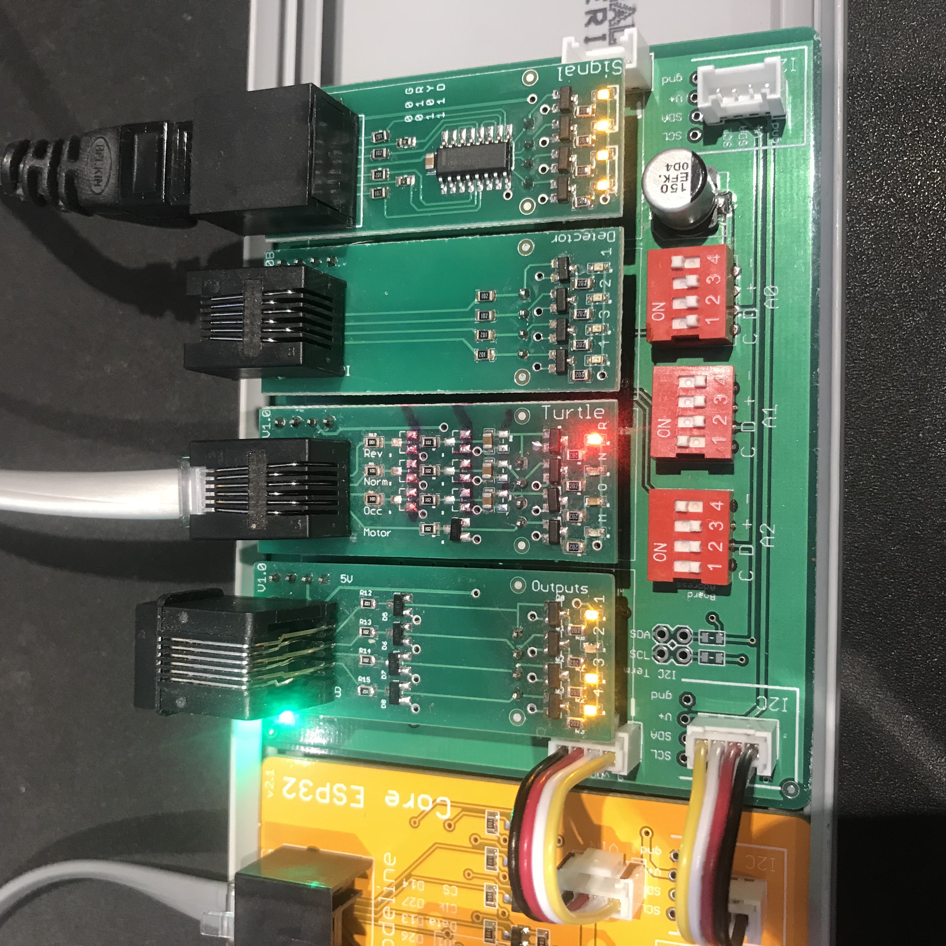
This IO board is based on the MAX7311/12 16 bit IO Expander, with a a bank of 4x I/O Boards. These IOBs contain buffered LED drivers connected to LEDs that show the status of the I/O lines in real time. They also contain the needed circuitry to drive / sense the appliances connected to them. See
- IOB-Inputs 4x buffered inputs
- IOB-Outputs 4x buffered outputs
- IOB-Turtle 1x buffered output and 3x buffered inputs
- IOB-Signal 2x RGB signal head driver (Dark, Stop, Approach, Clear)
Each board provides a latched set of 16x IO points, with each point being software selectable to be either an input or an output. The individual points are reasonably protected from the environment, and can sink 10 mA each (with the MAX7312, they can also drive ~20mA). By using active low inputs and outputs, the effects of environmental noise are reduced - remote sensors only need to ground an I/O point to register activity.
Communication Protocol
Simple I2C 16-bit Reads and Writes:
uint16_t I2Cexpander::read7311() {
    uint16_t data = 0;
    Wire.beginTransmission(_i2c_address);
    Wire.write(REGISTER_7311INPUT);
    Wire.endTransmission();
    // Wire.beginTransmission(_i2c_address);
    Wire.requestFrom(_i2c_address, (uint8_t)2);
    if(Wire.available()) {
        data = Wire.read();
    }
    if(Wire.available()) {
        data |= (Wire.read() << 8);
    }
    // Wire.endTransmission();
    return data;
}

void I2Cexpander::write7311(uint16_t data) {
    data = data | _config;
    Wire.beginTransmission(_i2c_address);
    Wire.write(REGISTER_7311OUTPUT);
    Wire.write(0xff & data);  //  low byte
    Wire.write(data >> 8);    //  high byte
    Wire.endTransmission();
}
See I2Cexpander-lib for a more complete interface library.
Addressing
| AD2 | AD1 | AD0 | A6 | A5 | A4 | A3 | A2 | A1 | A0 | ADDRESS (HEX) |
|---|---|---|---|---|---|---|---|---|---|---|
| GND | SCL | GND | 0 | 0 | 1 | 0 | 0 | 0 | 0 | 0x20 |
| GND | SCL | V+ | 0 | 0 | 1 | 0 | 0 | 0 | 1 | 0x22 |
| GND | SDA | GND | 0 | 0 | 1 | 0 | 0 | 1 | 0 | 0x24 |
| GND | SDA | V+ | 0 | 0 | 1 | 0 | 0 | 1 | 1 | 0x26 |
| V+ | SCL | GND | 0 | 0 | 1 | 0 | 1 | 0 | 0 | 0x28 |
| V+ | SCL | V+ | 0 | 0 | 1 | 0 | 1 | 0 | 1 | 0x2A |
| V+ | SDA | GND | 0 | 0 | 1 | 0 | 1 | 1 | 0 | 0x2C |
| V+ | SDA | V+ | 0 | 0 | 1 | 0 | 1 | 1 | 1 | 0x2E |
| GND | SCL | SCL | 0 | 0 | 1 | 1 | 0 | 0 | 0 | 0x30 |
| GND | SCL | SDA | 0 | 0 | 1 | 1 | 0 | 0 | 1 | 0x32 |
| GND | SDA | SCL | 0 | 0 | 1 | 1 | 0 | 1 | 0 | 0x34 |
| GND | SDA | SDA | 0 | 0 | 1 | 1 | 0 | 1 | 1 | 0x36 |
| V+ | SCL | SCL | 0 | 0 | 1 | 1 | 1 | 0 | 0 | 0x38 |
| V+ | SCL | SDA | 0 | 0 | 1 | 1 | 1 | 0 | 1 | 0x3A |
| V+ | SDA | SCL | 0 | 0 | 1 | 1 | 1 | 1 | 0 | 0x3C |
| V+ | SDA | SDA | 0 | 0 | 1 | 1 | 1 | 1 | 1 | 0x3E |
| GND | GND | GND | 0 | 1 | 0 | 0 | 0 | 0 | 0 | 0x40 |
| GND | GND | V+ | 0 | 1 | 0 | 0 | 0 | 0 | 1 | 0x42 |
| GND | V+ | GND | 0 | 1 | 0 | 0 | 0 | 1 | 0 | 0x44 |
| GND | V+ | V+ | 0 | 1 | 0 | 0 | 0 | 1 | 1 | 0x46 |
| V+ | GND | GND | 0 | 1 | 0 | 0 | 1 | 0 | 0 | 0x48 |
| V+ | GND | V+ | 0 | 1 | 0 | 0 | 1 | 0 | 1 | 0x4A |
| V+ | V+ | GND | 0 | 1 | 0 | 0 | 1 | 1 | 0 | 0x4C |
| V+ | V+ | V+ | 0 | 1 | 0 | 0 | 1 | 1 | 1 | 0x4E |
| GND | GND | SCL | 0 | 1 | 0 | 1 | 0 | 0 | 0 | 0x50 |
| GND | GND | SDA | 0 | 1 | 0 | 1 | 0 | 0 | 1 | 0x52 |
| GND | V+ | SCL | 0 | 1 | 0 | 1 | 0 | 1 | 0 | 0x54 |
| GND | V+ | SDA | 0 | 1 | 0 | 1 | 0 | 1 | 1 | 0x56 |
| V+ | GND | SCL | 0 | 1 | 0 | 1 | 1 | 0 | 0 | 0x58 |
| V+ | GND | SDA | 0 | 1 | 0 | 1 | 1 | 0 | 1 | 0x5A |
| V+ | V+ | SCL | 0 | 1 | 0 | 1 | 1 | 1 | 0 | 0x5C |
| V+ | V+ | SDA | 0 | 1 | 0 | 1 | 1 | 1 | 1 | 0x5E |
| SCL | SCL | GND | 1 | 0 | 1 | 0 | 0 | 0 | 0 | 0xA0 |
| SCL | SCL | V+ | 1 | 0 | 1 | 0 | 0 | 0 | 1 | 0xA2 |
| SCL | SDA | GND | 1 | 0 | 1 | 0 | 0 | 1 | 0 | 0xA4 |
| SCL | SDA | V+ | 1 | 0 | 1 | 0 | 0 | 1 | 1 | 0xA6 |
| SDA | SCL | GND | 1 | 0 | 1 | 0 | 1 | 0 | 0 | 0xA8 |
| SDA | SCL | V+ | 1 | 0 | 1 | 0 | 1 | 0 | 1 | 0xAA |
| SDA | SDA | GND | 1 | 0 | 1 | 0 | 1 | 1 | 0 | 0xAC |
| SDA | SDA | V+ | 1 | 0 | 1 | 0 | 1 | 1 | 1 | 0xAE |
| SCL | SCL | SCL | 1 | 0 | 1 | 1 | 0 | 0 | 0 | 0xB0 |
| SCL | SCL | SDA | 1 | 0 | 1 | 1 | 0 | 0 | 1 | 0xB2 |
| SCL | SDA | SCL | 1 | 0 | 1 | 1 | 0 | 1 | 0 | 0xB4 |
| SCL | SDA | SDA | 1 | 0 | 1 | 1 | 0 | 1 | 1 | 0xB6 |
| SDA | SCL | SCL | 1 | 0 | 1 | 1 | 1 | 0 | 0 | 0xB8 |
| SDA | SCL | SDA | 1 | 0 | 1 | 1 | 1 | 0 | 1 | 0xBA |
| SDA | SDA | SCL | 1 | 0 | 1 | 1 | 1 | 1 | 0 | 0xBC |
| SDA | SDA | SDA | 1 | 0 | 1 | 1 | 1 | 1 | 1 | 0xBE |
| SCL | GND | GND | 1 | 1 | 0 | 0 | 0 | 0 | 0 | 0xC0 |
| SCL | GND | V+ | 1 | 1 | 0 | 0 | 0 | 0 | 1 | 0xC2 |
| SCL | V+ | GND | 1 | 1 | 0 | 0 | 0 | 1 | 0 | 0xC4 |
| SCL | V+ | V+ | 1 | 1 | 0 | 0 | 0 | 1 | 1 | 0xC6 |
| SDA | GND | GND | 1 | 1 | 0 | 0 | 1 | 0 | 0 | 0xC8 |
| SDA | GND | V+ | 1 | 1 | 0 | 0 | 1 | 0 | 1 | 0xCA |
| SDA | V+ | GND | 1 | 1 | 0 | 0 | 1 | 1 | 0 | 0xCC |
| SDA | V+ | V+ | 1 | 1 | 0 | 0 | 1 | 1 | 1 | 0xCE |
| SCL | GND | SCL | 1 | 1 | 0 | 1 | 0 | 0 | 0 | 0xD0 |
| SCL | GND | SDA | 1 | 1 | 0 | 1 | 0 | 0 | 1 | 0xD2 |
| SCL | V+ | SCL | 1 | 1 | 0 | 1 | 0 | 1 | 0 | 0xD4 |
| SCL | V+ | SDA | 1 | 1 | 0 | 1 | 0 | 1 | 1 | 0xD6 |
| SDA | GND | SCL | 1 | 1 | 0 | 1 | 1 | 0 | 0 | 0xD8 |
| SDA | GND | SDA | 1 | 1 | 0 | 1 | 1 | 0 | 1 | 0xDA |
| SDA | V+ | SCL | 1 | 1 | 0 | 1 | 1 | 1 | 0 | 0xDC |
| SDA | V+ | SDA | 1 | 1 | 0 | 1 | 1 | 1 | 1 | 0xDE |
This technical documentation is licensed under the CERN Open Hardware Licence v1.2