PCR-Badge-2015
PCR-Badge-2015
A DIY convention badge for the PCR 2015 Club Car Convention
|
|
|
|
|
Download PartsList.pdf - Documentation
1-ERRATA
The best laid plans … sigh.
We ran into two problems with this project - one easy to fix and the other, well, not so much…
-
The grab bag batch of Red LEDs (1 pound for a dollar or some such bargain…) was too good to be true - 20% of the LEDs turned out to be defective - including all three I used on the initial bring-up board. If nothing else, it was an interesting debugging experience and a lesson in the true cost of being cheap :-)
-
Once I got the blinking LEDs sorted out, everything else tested out OK - except for the IR sensor. More debugging, trace following, scope probes - all showed that “it should be working” - except it didn’t. Until the AHA! moment when I realized that, no matter how many times I tried to analogRead(D7), it wouldn’t work (Doh!). This one is all my fault - I was revising a schematic late at night, just before the fab deadline, trying to squeeze out just one more IO pin to do something interesting, while at the same time cleaning up the board layout. Obviously by moving some connections from here to there - after all, they are just labels on the CAD screen…
This could be “fixed” by cutting traces and running jumper wires, which, while it would certainly make the project more realistic, wouldn’t make any friends at the convention. I decided to drop the feature and pull the unused parts out of the kit bags. Sigh.
We distributed 20 kits at the show - enough for us to almost recoup our BOM costs - and had two people spend their afternoon assembling their kits - one of whom had never soldered before! (his badge worked the first time, too!)
Success!
2-PCR
PCR Club Car Convention 2015
‘Duino Demo Board
Once a year, the model railroaders in Northern California and Nevada (officially, the Pacific Coast Region of the National Model Railroad Association) host a convention. 2015’s theme was The Club Car - a nod towards the many vibrant railroad clubs in the area.
Coincidentally, the convention overlapped the Bay Area Maker Faire’s time slot, which made for some very long days indeed!
Because of the juxtaposition with the Faire, railnerd and I decided to produce an assemble it yourself “badge” for the railroad convention - after all, model train buffs are all makers of one sort or another - and getting into animations and layout control with a ‘duino is a natural progression from controlling trains with a packet network on the rails (via Digital Command Control)…
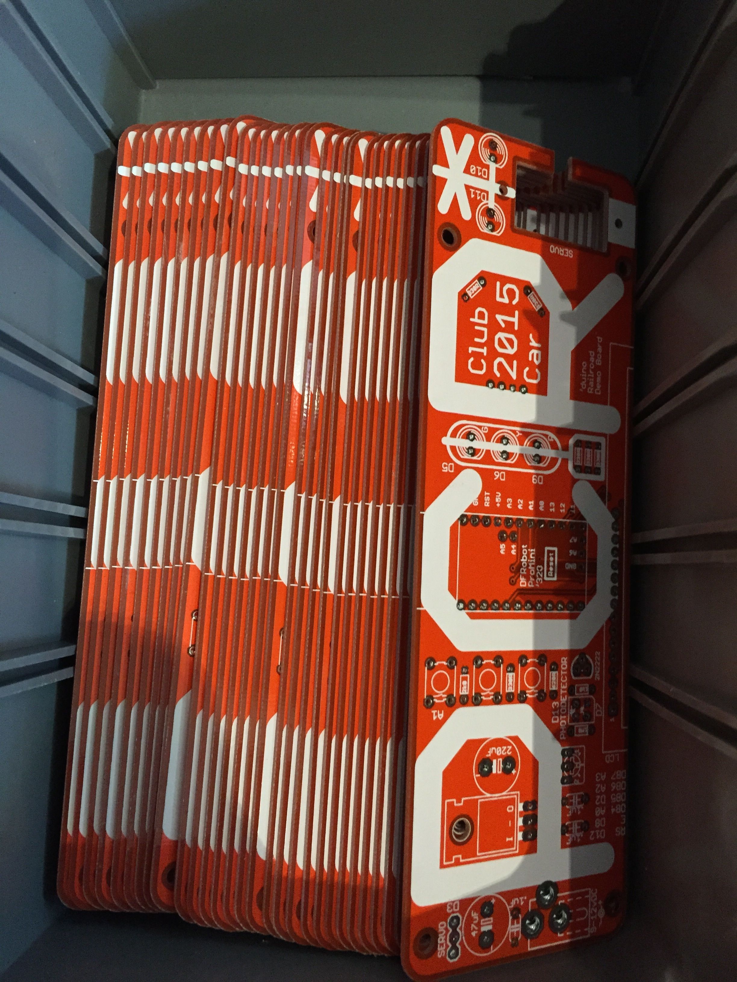
With judicious ebay and alibaba sleuthing, along with raiding some old stockpiles and a run to a local surplus store, we managed to produce a 30-board run with a total per-board BOM cost of about $20! (ICStation had 1602 LCDs for ~$3.10/ea, czb6721960@ebay had Pro Mini atmega328 5V 16M’s for $2.50, etc…)
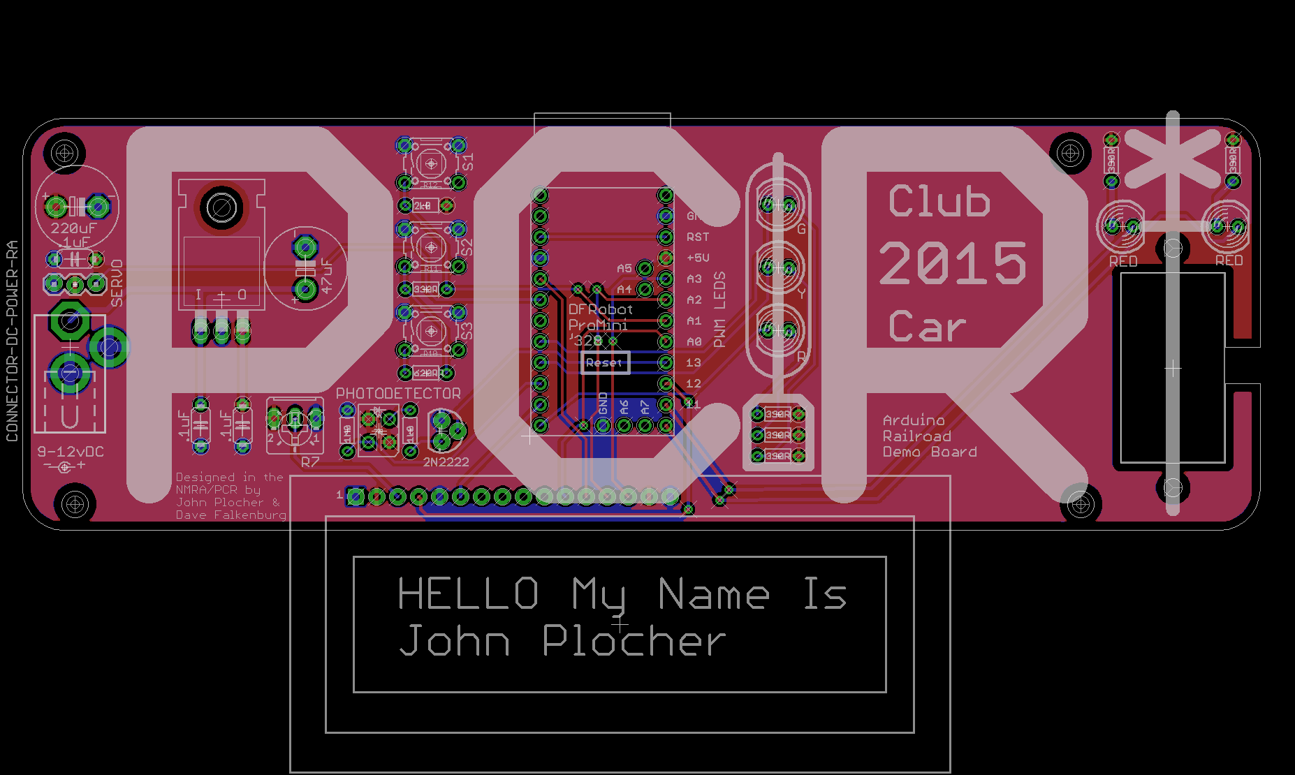
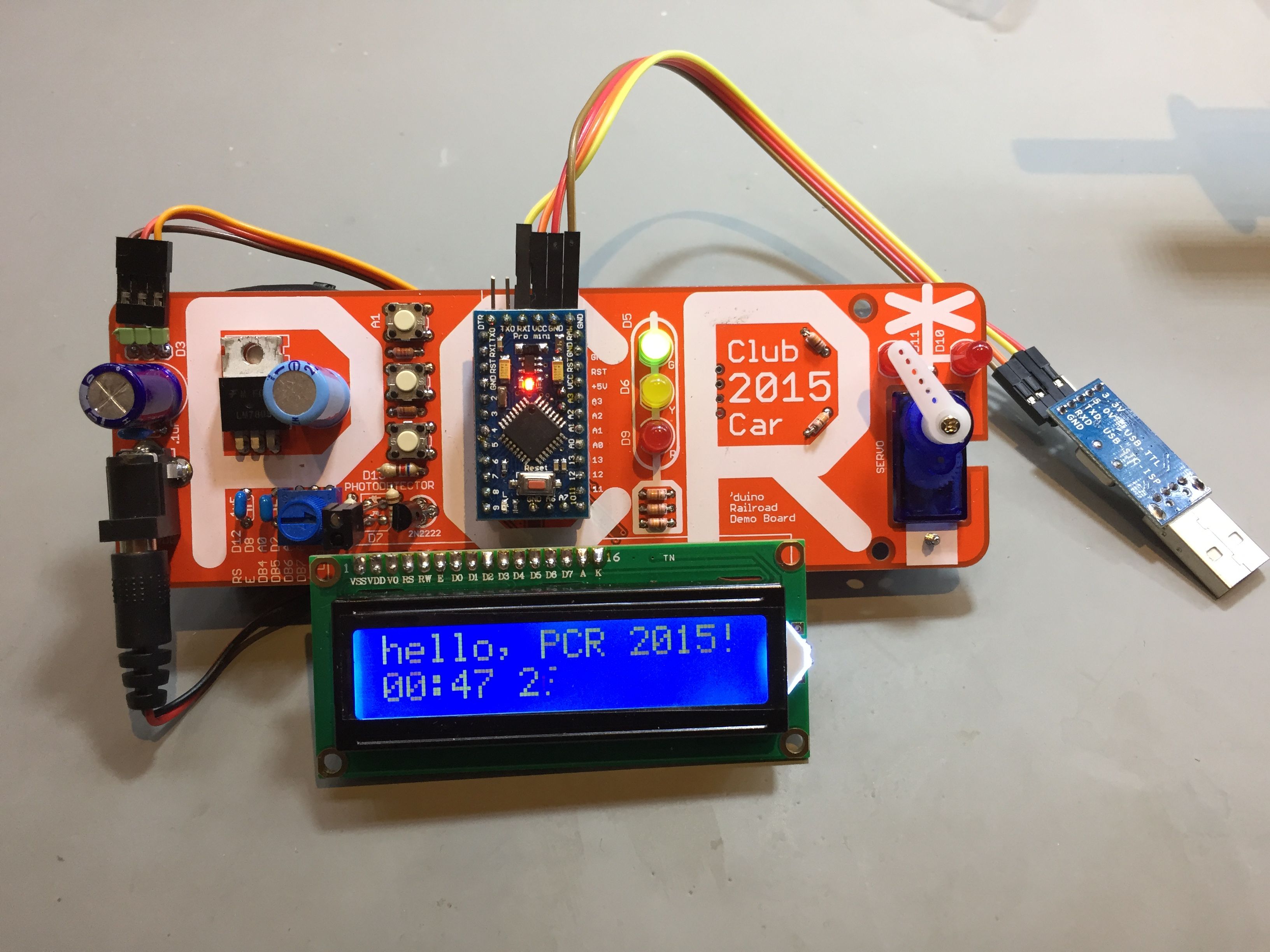
The PCR demo/badge board is a foundation for experimentation and learning about ‘duino programming and model railroad applications.
It includes
- An Arduino-compatible “DFR-pro-mini” clone module
- A regulated 5v power supply
- 9v battery (good for 6-8 hours runtime…) and adapter
- 3x pushbuttons
- 5x LEDs, arranged as a grade crossing and a signal head
- A servo, and
- A 2x16 LCD display
- I2C connector for access to expanded IO devices
Brought to you by Railnerd and SPCoast, sources for DIY model railroad electronics ideas
3-AssemblyInstructions
PCR Club Car Convention 2015 ‘Duino Demo Board
The PCR board is intended to be a foundation for experimentation and learning about ‘duino programming and model railroad applications. It provides
- An Arduinocompatible “DFRpromini” module
- A regulated 5v power supply
- 9v battery (good for only 68 hours runtime…) and adapter
- 3x pushbuttons
- 5x LEDs, arranged as a grade crossing and a signal head
- A servo, and
- A 2x16 LCD display
- I2C connector for access to expanded IO devices
Brought to you by SPCoast, a source for DIY model railroad electronics ideas
Assembly instructions
1. Assemble the Pro-Mini
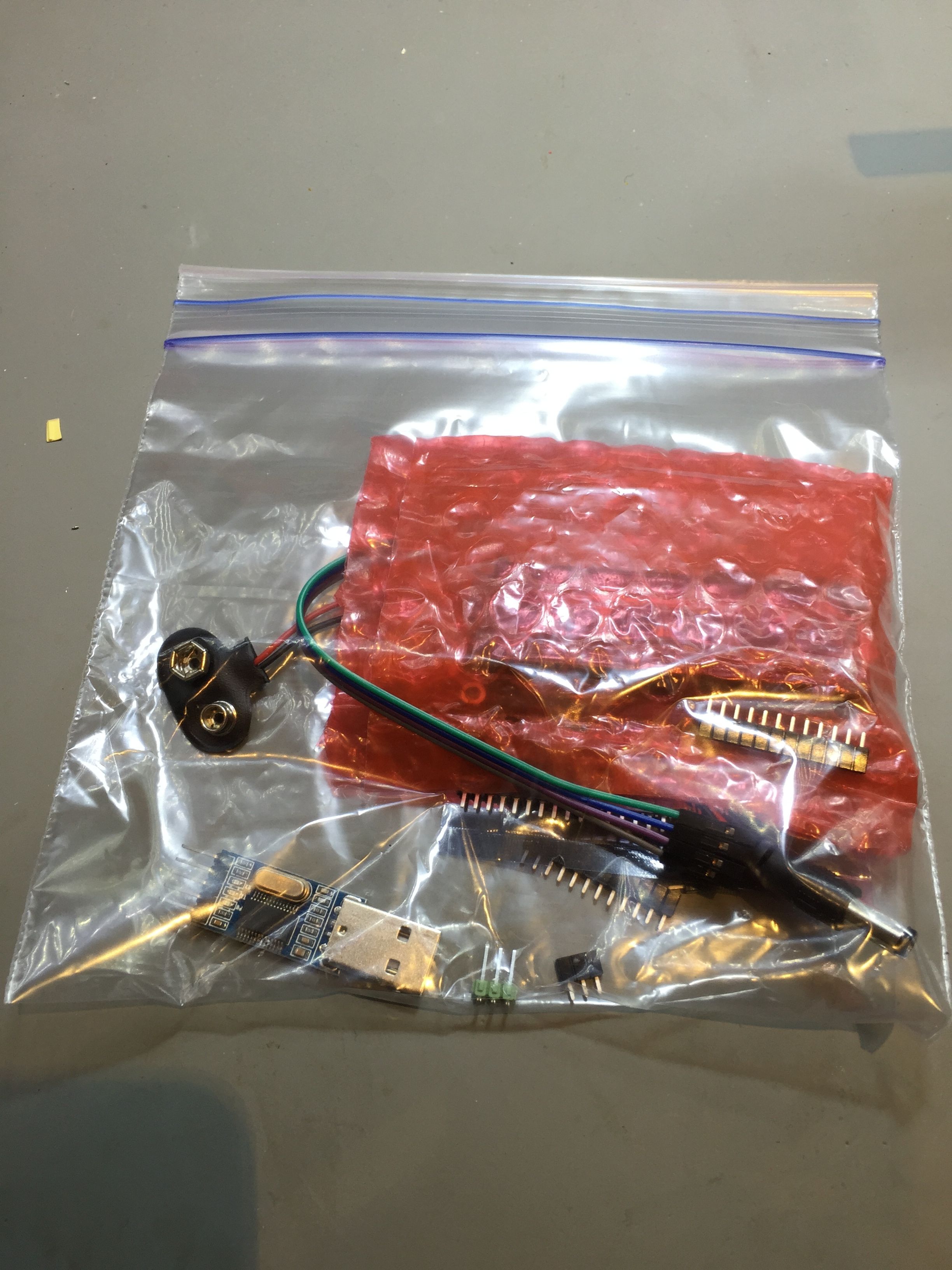
- find two rows of 12x pins, one row of 3x pins and one row of 2x pins
- using a breadboard to align the 12x rows, solder them to the bottom of the ProMini
- (Optional)
- The 3pin row exposes the A6 and A7 Analog InputOnly pins which are not used on the demo board it is OK to not install them. Installing them on the bottom makes the ProMini not work in a breadboard.
- Align the 3x row, solder it to the ProMini
- The 2pin row exposes the I2C signals from A4 and A5. I2C isn’t used by the demo board, though it does connect them (if present) to a 4pin connector for your own use. As above, installing these pins on the bottom makes the ProMini not fit into a breadboard, which is the reason this step is optional.
- Insert the 2x row holding it in place with a short piece of blue tape and solder it carefully to the ProMini
- find the 6x row if “right angle” pins, solder it to the TOP of the ProMini.
- Set the completed ProMini aside for now
2. Assemble the Demo Board
Working through the parts list, install
- The capacitors (C1 & C4 are polarized the long lead goes into the “+” hole)
- The resistors skip R6 & R8 (1K and 1M). Note that the 2K0 R12 (next to the top pushbutton) and the 620R R6 (near the bottom pushbutton) have different color bands than the rest (which are 330R):
- 330R: Orange Orange Brown
- 620R: Blue Red Brown
- 2K0: Red Black Red
- The potentiometer mounts under the “P”; it needs its pins gently straightened/aligned with a needlenose pliers
- The servo connector. Use either the 3pin rightangle or make a 3pin straight from the extra ProMini pins.
- The voltage regulator VR1 carefully bend the leads 90 degrees where they change shape.
- The power connector careful the large pins/holes get hot when soldering; be sure not to burn your fingers!
- Sw1, Sw2, Sw3 you may need to clip off an unused 5th pin (the one connected to the top of the button) before you can insert them into the 4hole footprints.
- (The PhotoDetector feature doesn’t work, and is left unpopulated) Leave the 1M, photodiode/IRLED and 2N2222 device spots empty.
- The female connectors (12x, 12x, 3x, 2x) for the ProMini are easily aligned by plugging the actual ProMini into them as they are sitting on the board; a strip of blue tape will hold everything onto the board as you turn it over to solder the pins. Solder one pin, then use your finger to push everything tight onto the board as you solder a second pin in the other corner. Once the connectors are flush and square, solder the rest of the pins. If you didn’t install the 3x and 2x pins to the ProMini, you don’t need to install the mating 3x and 2x sockets either.
- The 16 pin LCD connector. Start with one pin, ensure flush and flat, solder a second one, then the rest…
- The LEDs 2x Red for the crossbucks and 1x each Red, Yellow and Green for the Signal mast. Flat = short lead = “”, long lead = “+”
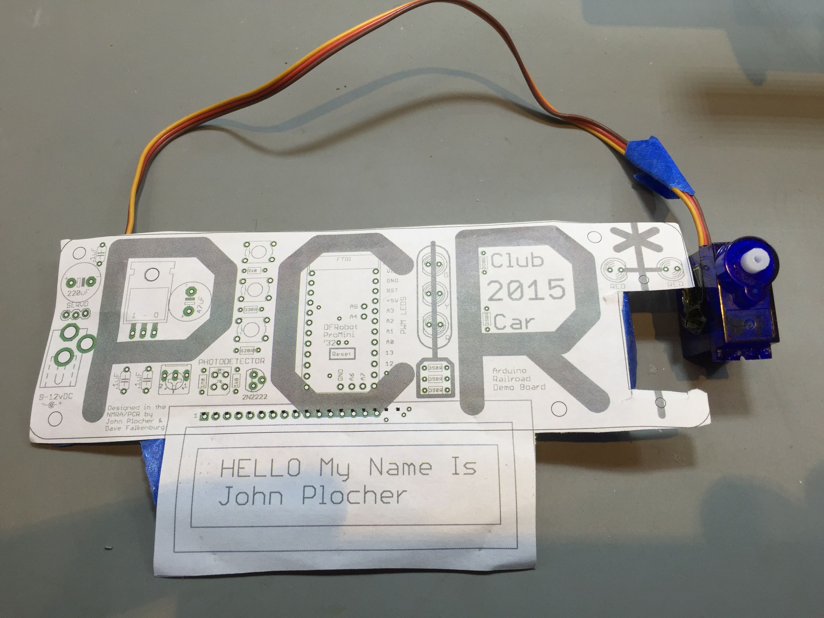
- The Servo. You can screw it directly to the demo board with the provided screws if desired. You can choose which “horn” to attach to the servo to match the application you will use it for. In this situation, I used the long, single ended arm to represent a crossing gate that goes up and down… Don’t attach a horn to the servo until you run the demo sketch it centers the servo so you can align the horn in a pleasing orientation.
3. Assemble the LCD
- Solder the 16x pin strip to the LCD, making sure it is flat and flush.
4. Assemble the USB Programmer
- Find the 4wire harness
- Connect one end to 5.0v, TxD, RxD and GND. Make note of the colors…
5. Connect the pieces
- Plug the ProMini into the demo board if you haven’t already
- Plug the servo into the 3pin servo connector (alignment color code is printed on back of the board)
- Plug in the LCD display
- Connect the USB programmer to the ProMini
- 5.0v goes to VCC
- Gnd goes to Gnd
- TxD goes to RxD, and
- RxD goes to TxD
- Attach the 9v battery to the battery cable (but don’t yet plug it into the board)
- Install (if needed) the Prolific PL2303HX drivers for your OS
- Windows Drivers
- Mac Drivers
- Linux Kernel 2.4.31 and above already includes builtin drivers for PL2303 (VID_067B&PID_2303)
6. Try it out
- Load the demo sketch in your Browser and set the properties correctly
- https://codebender.cc/sketch:112378
- select Pro Mini (5v, 16MHz, ATmega ‘328)
- select /dev/cu.usbserial (or whatever the Prolific 2303 enumerates as…)
- Modify the GREETING to include your name (you may want to clone the sketch)
- select “Run on Arduino”. When the blue bar gets more than 1⁄2 way across, press the RESET button on the ProMini to tell it to run the bootloader
- If you don’t get any errors,
- you should see your name on the LCD,
- The top button raises the “crossing gate”
- The middle button turns on and off the crossing flashers
- The bottom button lowers the gate.
- You can attach a horn to the servo if you want lower the gate by pressing the bottom button, then attach the horn so it extends horizontally, using the remaining tiny screw that came with the servo.
This technical documentation is licensed under the CERN Open Hardware Licence v1.2

