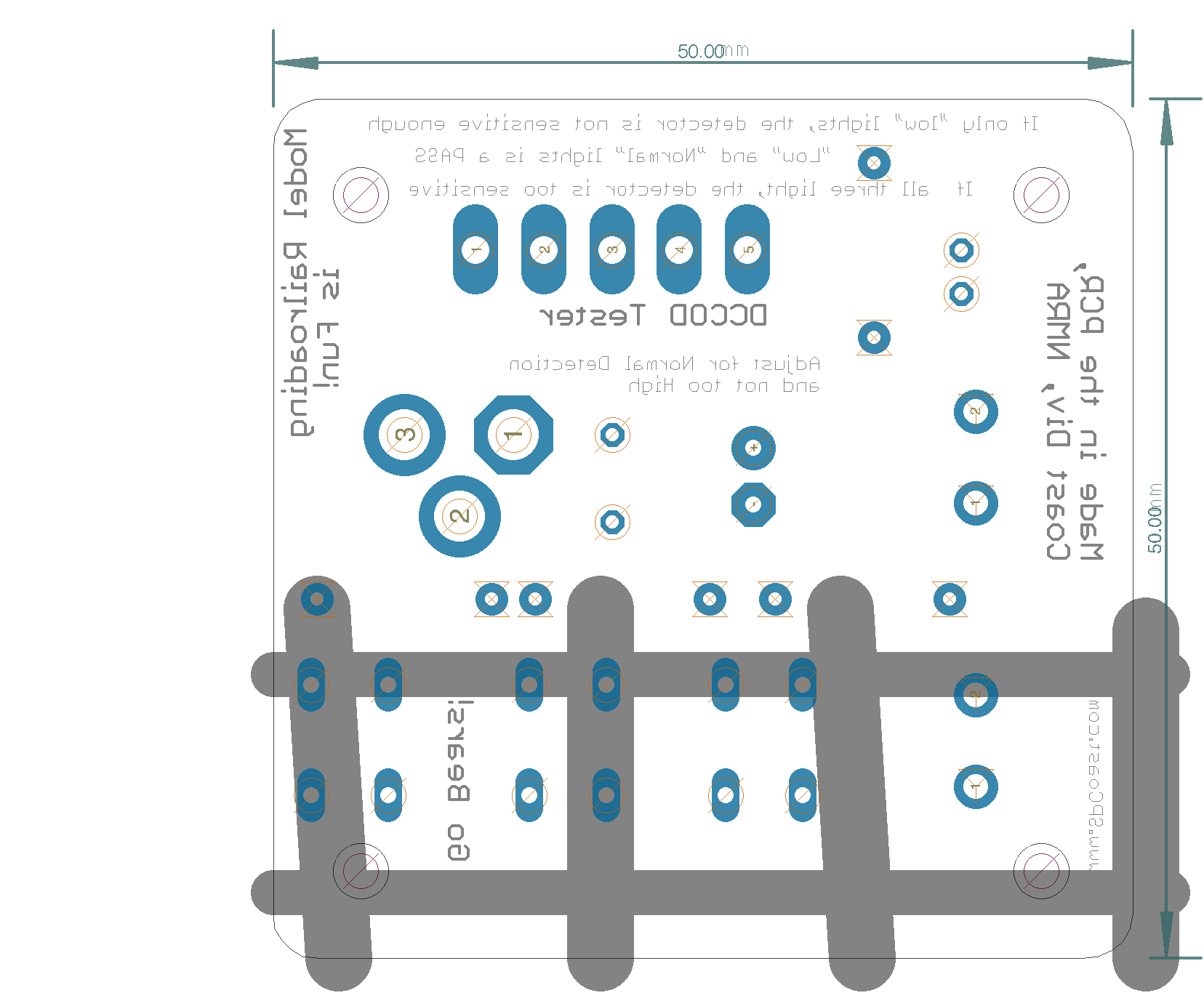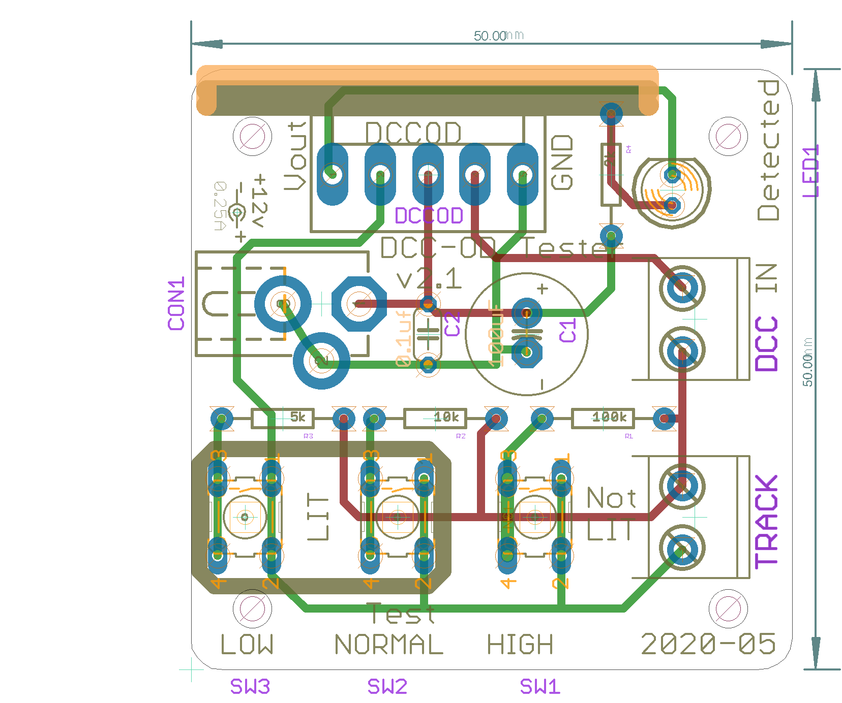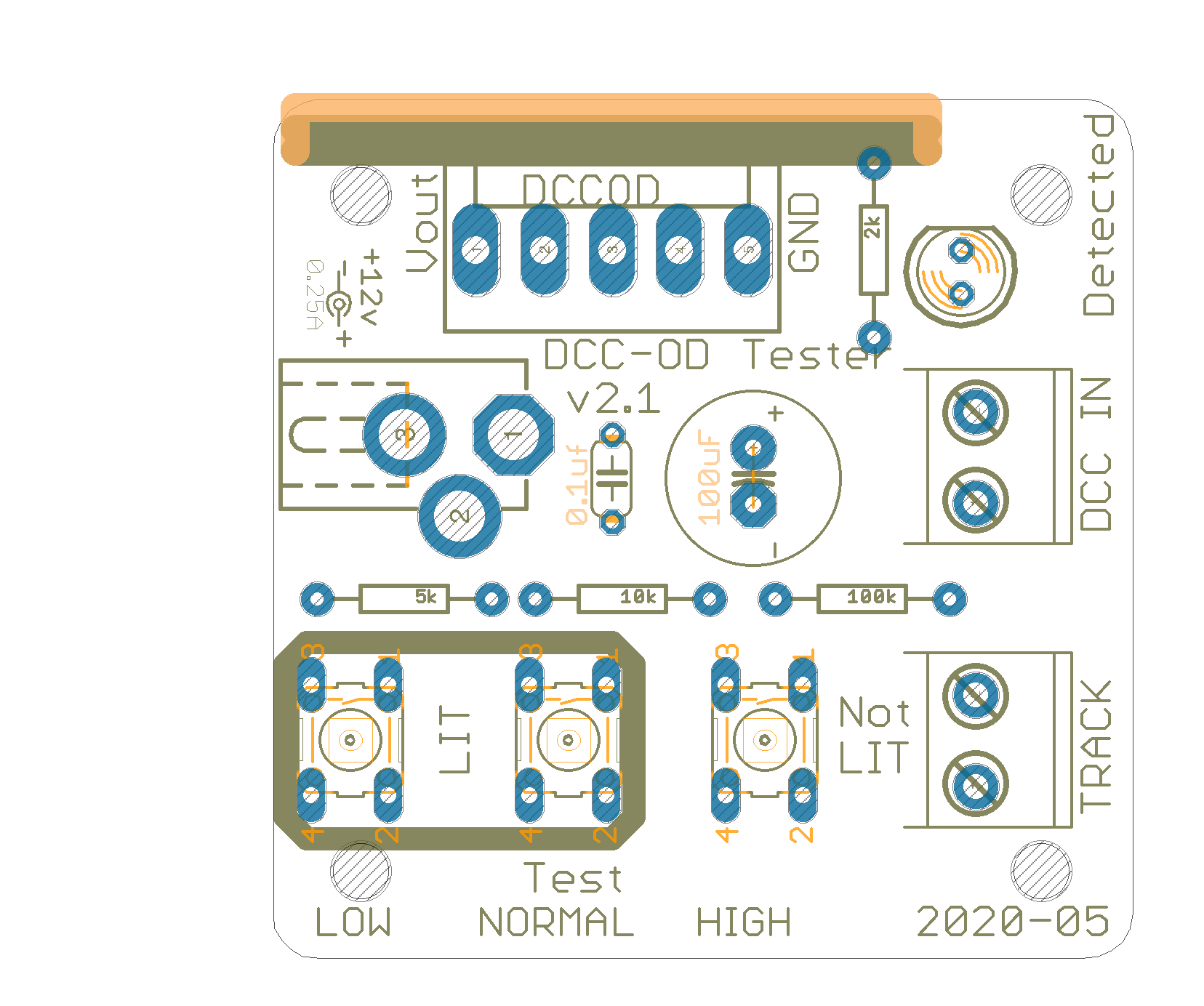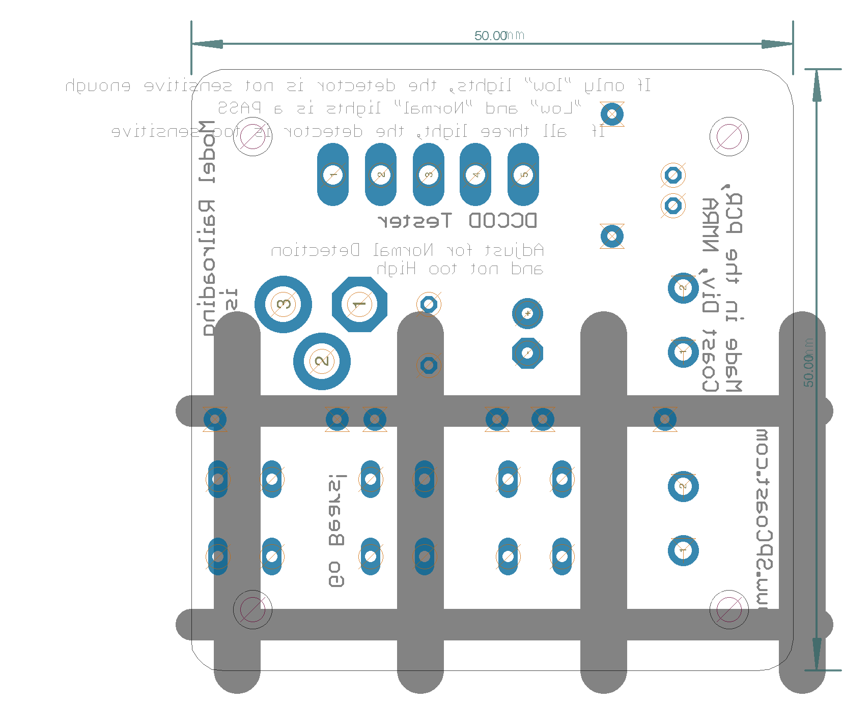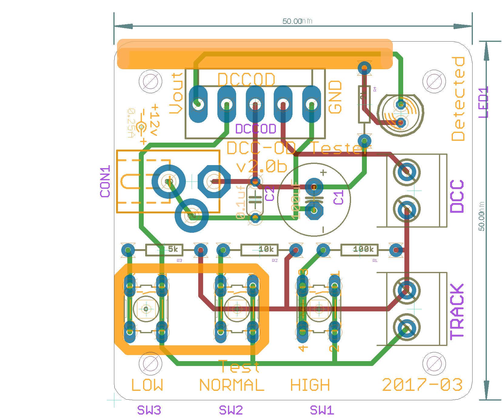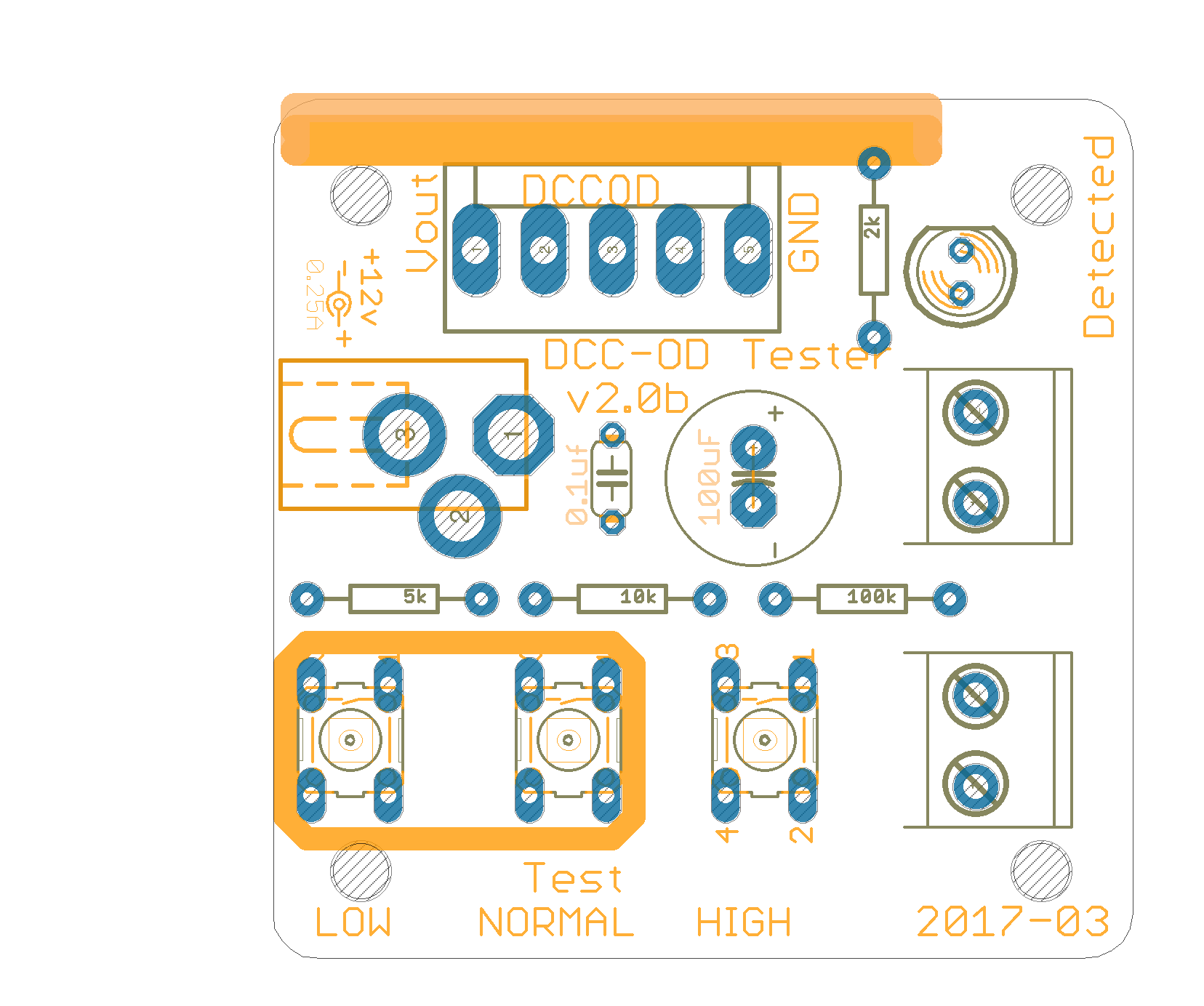
MRCS-odTester
A simple bench test board for Chubb\'s DCC-OD and MRCS\' cpOD detectors.
Test and tune Occupancy Detectors on your workbench for low, normal or high sensitivity
Version 2.0:
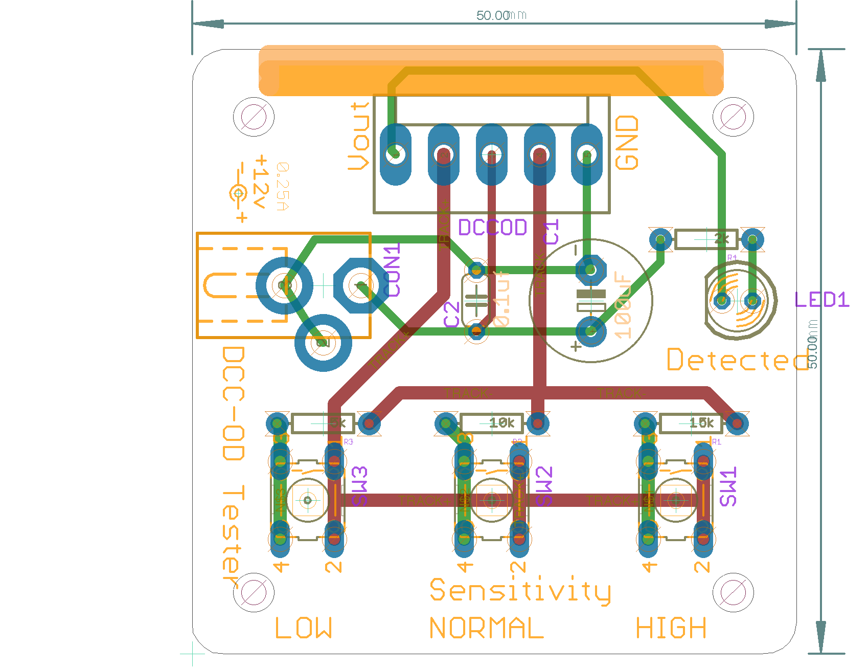
- Make the resistors pads 0.400 across. The standard red triangular benders only go down to 0.400 so bending to 0.300 requires doing it manually.
- Made the 100uF a 3.5x10 package to match what is in stock…
- Fixed silk screen TRACK and DCC
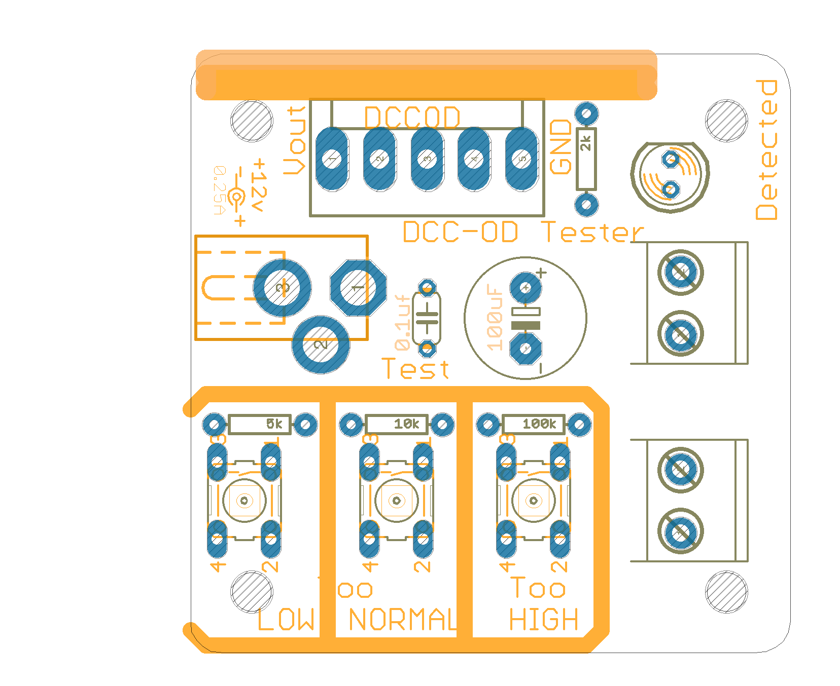
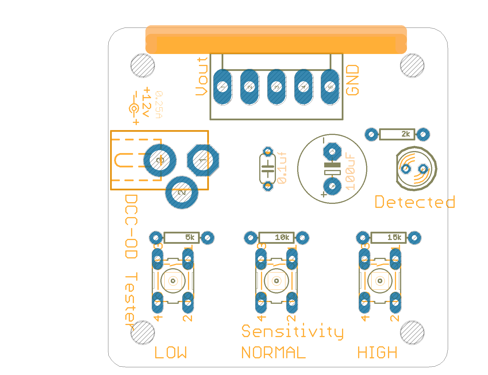
- Boxed the LOW and NORMAL buttons to indicate that they both chould trigger, and the HIGH one should not
MRCS-odTester Version 2.1
Not built
Test and tune Occupancy Detectors on your workbench for low, normal or high sensitivity
Version 2.0:
- Make the resistors pads 0.400 across. The standard red triangular benders only go down to 0.400 so bending to 0.300 requires doing it manually.
- Made the 100uF a 3.5x10 package to match what is in stock…
- Fixed silk screen TRACK and DCC
- Boxed the LOW and NORMAL buttons to indicate that they both chould trigger, and the HIGH one should not
|
|
|
UNPUBLISHED
MRCS-odTester Version 2.0
Not built
Test and tune Occupancy Detectors on your workbench for low, normal or high sensitivity
Version 2.0:
- Make the resistors pads 0.400 across. The standard red triangular benders only go down to 0.400 so bending to 0.300 requires doing it manually.
- Made the 100uF a 3.5x10 package to match what is in stock…
- Fixed silk screen TRACK and DCC
- Boxed the LOW and NORMAL buttons to indicate that they both chould trigger, and the HIGH one should not
|
|
|
UNPUBLISHED
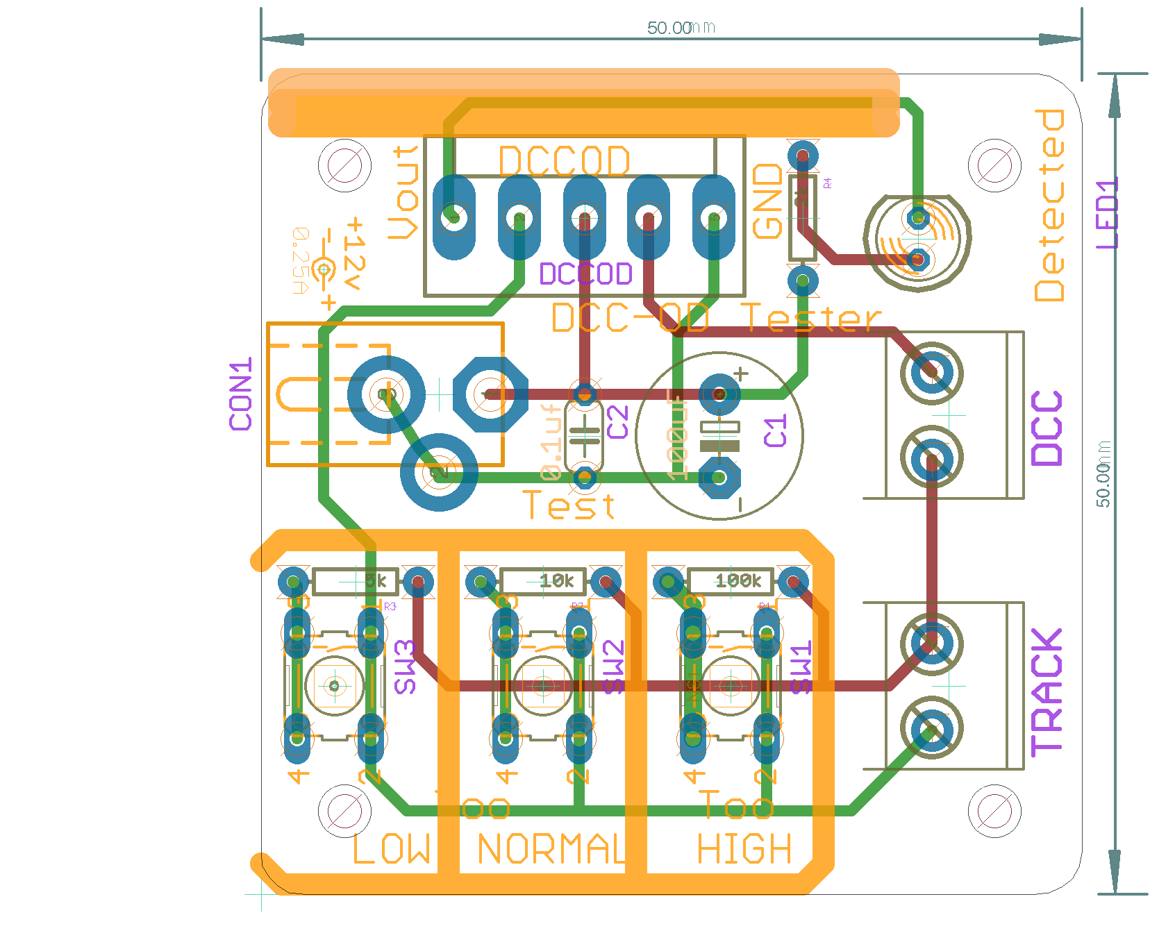
MRCS-odTester Version 1.1
Not built
Test and tune Occupancy Detectors on your workbench for low, normal or high sensitivity
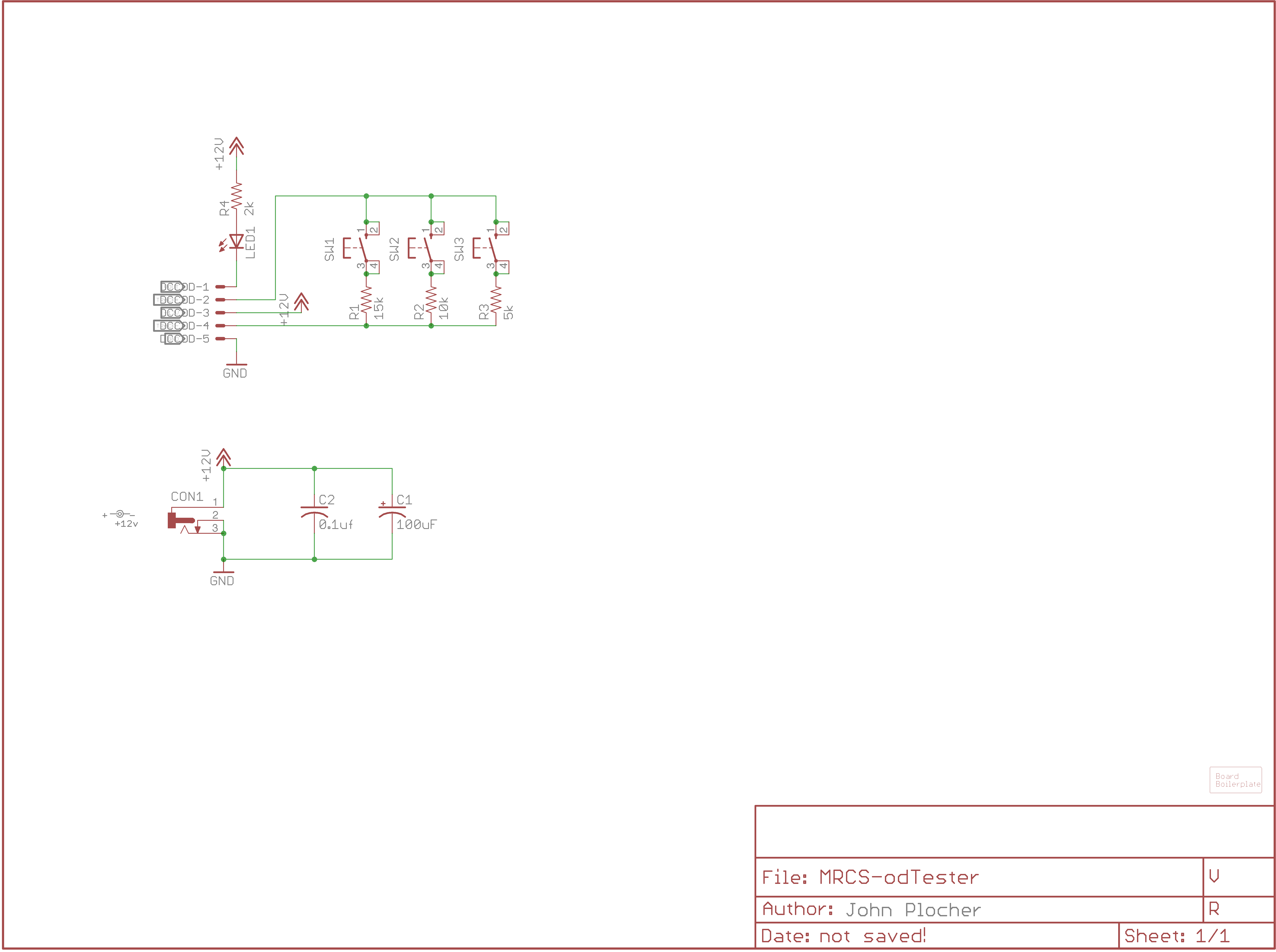
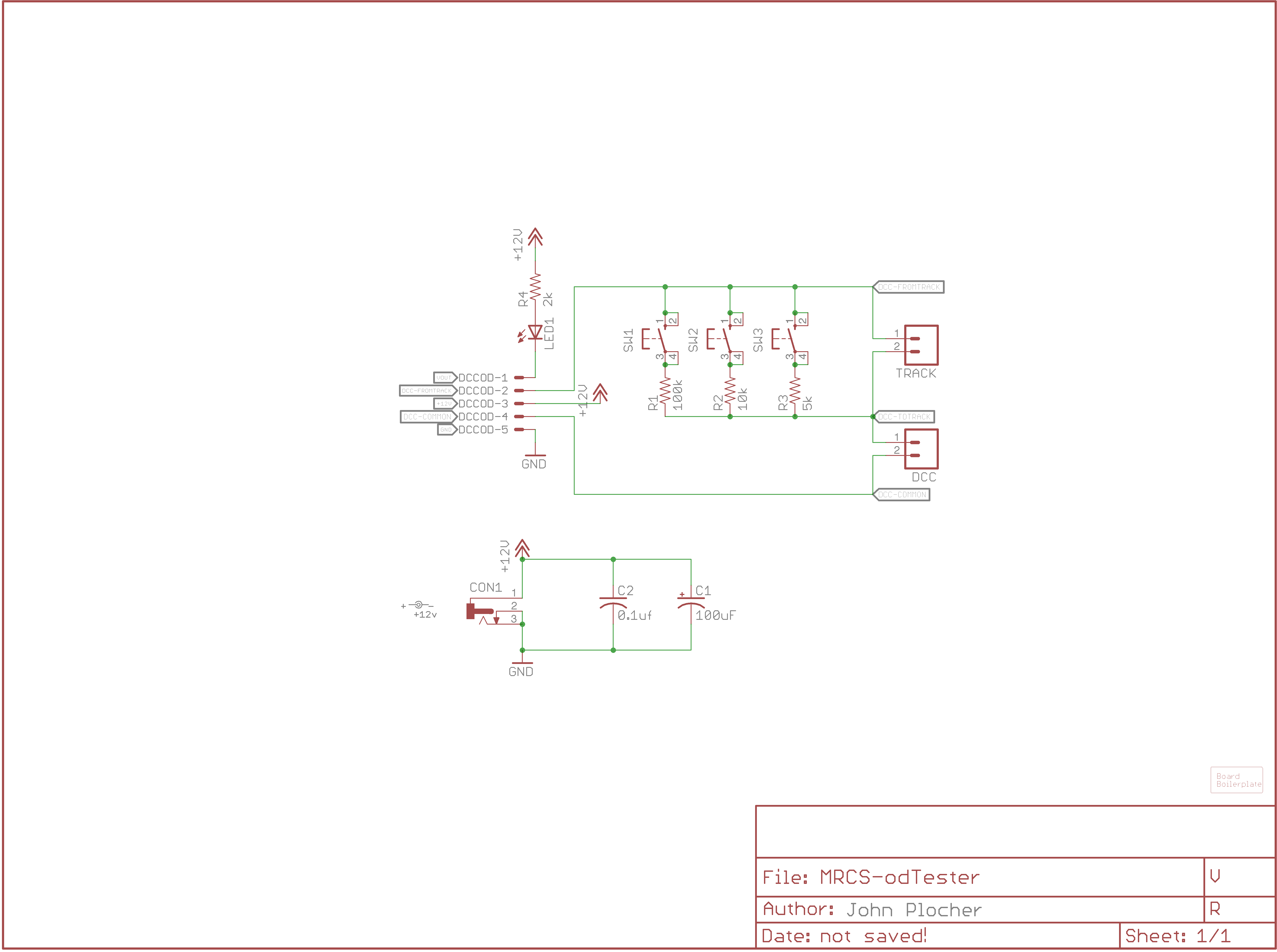
V1.1: external DCC source connector as well as external test track for testing rolling stock
|
|
|
UNPUBLISHED
Documentation
DCCOD Detector Tester
A simple bench test board for Chubb's DCC-OD and MRCS' cpOD detectors.
Theory:
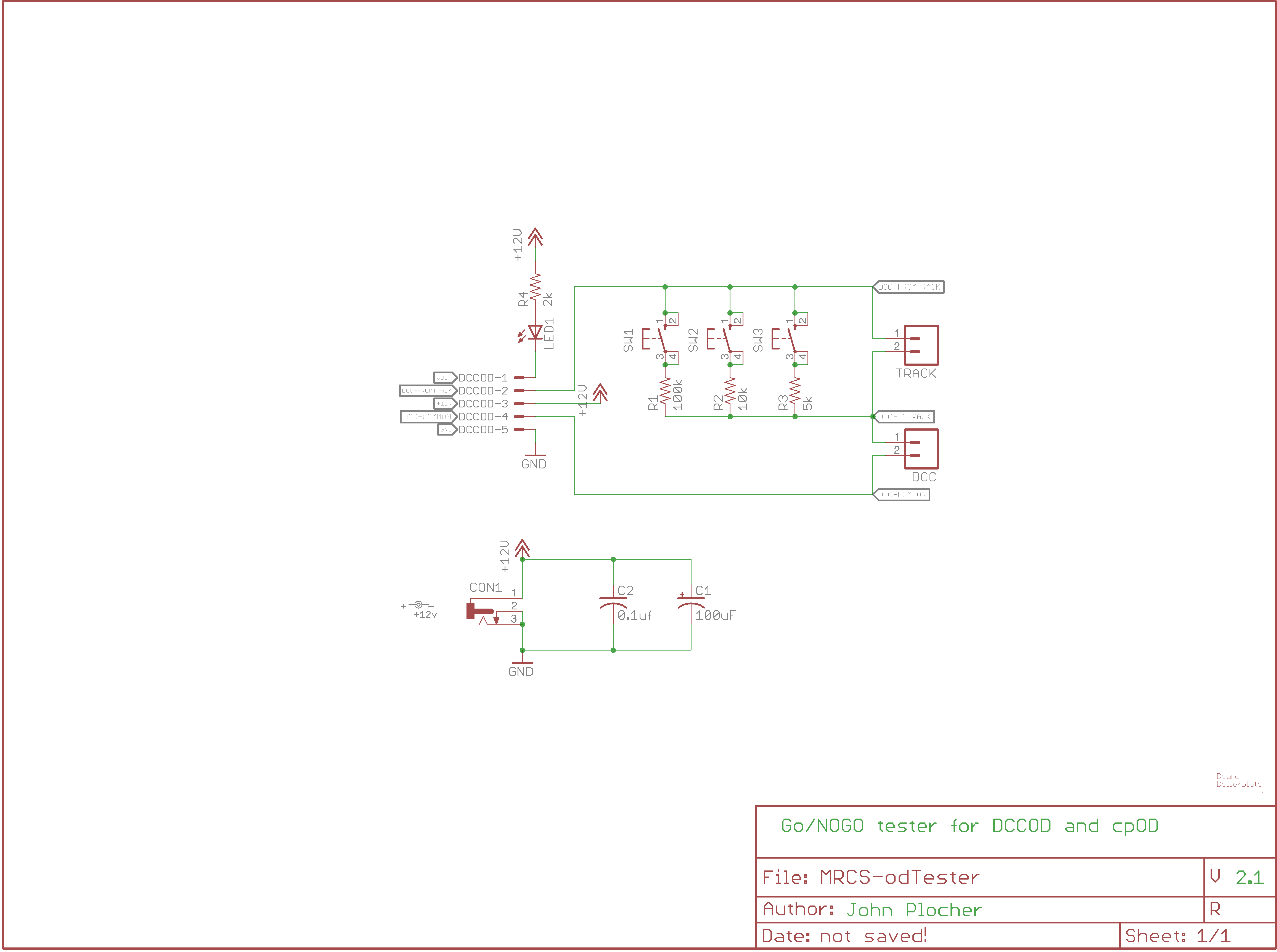
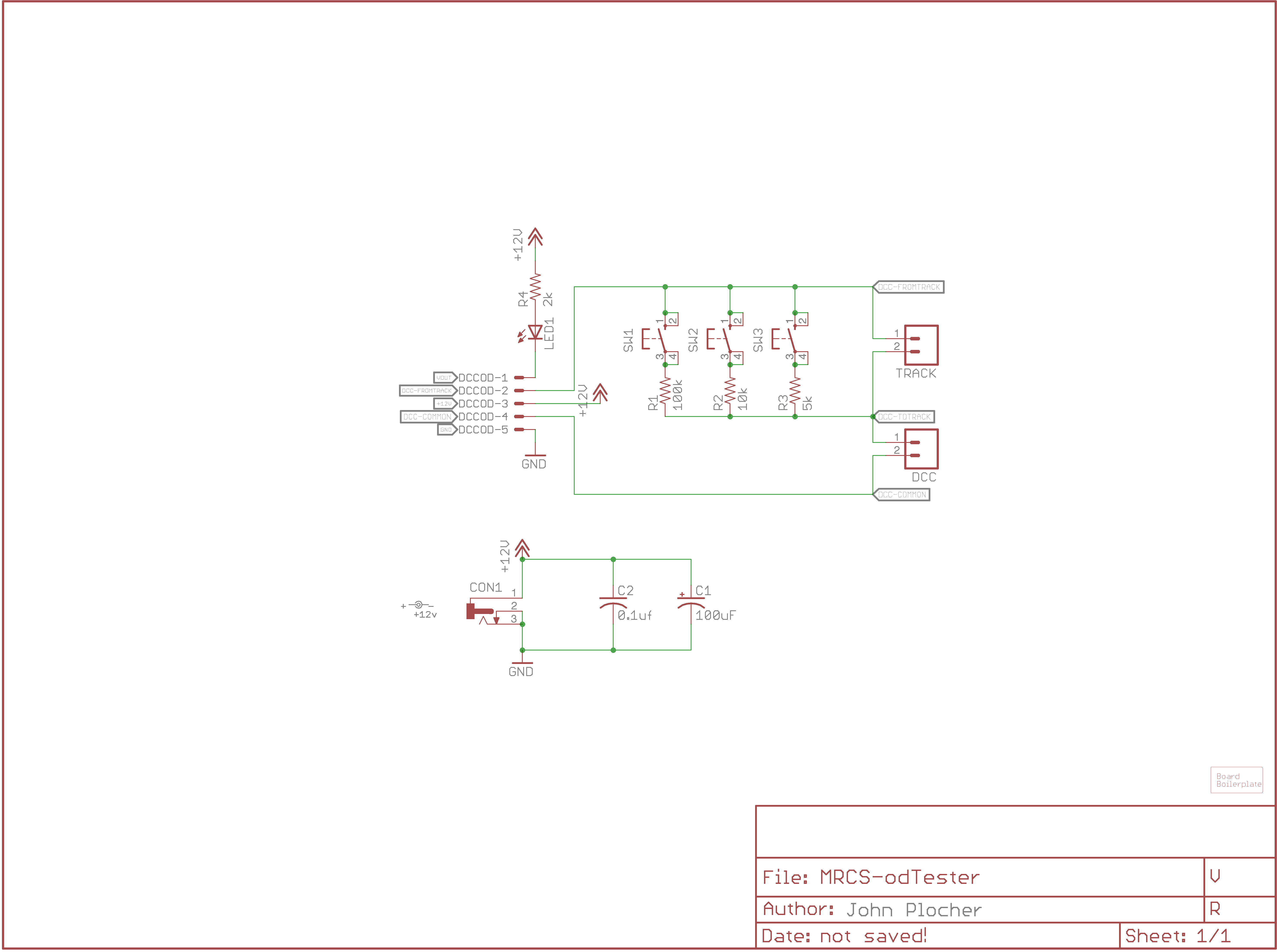
This board is designed to be a bench test unit for Chubb's DCCOD style detectors. A board is inserted into the test pins and the three buttons are pressed in sequence while observing the "detected" LED. A "good" board will light up with both the "low" and "normal" button presses, but not the "high" one. The DCCOD sensitivity can be adjusted in the jig to give the desired behavior.
A local test track can be optionally connected that enables the testing of specific locomotives and rolling stock simply by placing them on the track.
The values for R1, R2 and R3 should be chosen for the layout and locomotives in use - N-scale's small highly efficient motors will draw less current than a O- or G-scale, and will require greater sensitivity. Your wheelsets may provide 10K or 100K resistors, which should also inform your choices. The values below are astarting point; feel free to experiment. There is nothing wrong with choosing 100K as "normal" and 150K as "too high" as long as your choice of "turns" thru the DCCOD's pulse transformer can provide the detection. Start with "normal" matching your wheelset/rolling stock resistors, "low" being half of that, and high being 2x to 10x of normal...
Validate that your DCCOD can actually detect your chosen values by adjusting its potentiometer to its mose sensitive position and observing that the detected LED lights when the buttons are pressed.
Usage:
- Plug a DCCOD board to the DetectorTester.
- Connect to a 12v DC regulated power supply.
- Connect the output of a DCC booster to the DCC connector
- Press one of the pushbuttons to place a detectable load resistance across the simulated "track" for the detector to see - Sensitivity test values (choose to match your givens and druthers) - 5K resistance (~3mA) - 10K resistance (~1.5mA) - 100K resistance (~0.15mA) - 150K resistance (~0.1mA)
Use the following table to diagnose/adjust based on the whether the detection LED lights when the following buttons are pressed:
| LOW | NORMAL | HIGH | |
|---|---|---|---|
| OFF | OFF | OFF | Nothing lights, missing DCCOD, no DCC power, no DC power, poorly chosen R1,R2 and R3 |
| OFF | OFF | ON | Bad detector tester - check solder connections |
| OFF | ON | OFF | Bad detector tester - check solder connections |
| OFF | ON | ON | Bad detector board - check solder connections |
| ON | OFF | OFF | this DCCOD will have problems detecting a typical car resistance. Adjust DCCOD until NORMAL lights when pressed |
| ON | OFF | ON | Bad detector tester - check solder connections |
| ON | ON | OFF | this DCCOD is properly adjusted |
| ON | ON | ON | this DCCOD is potentially overly sensitive, and may false trigger. Lower the DCCOD sensitivity until this just extinguishes |
If any of the LEDs light when no buttons are pressed and nothing is connected to the external track connector, either the detector tester or the DCCOD is bad.
doc
DCCOD Detector Tester
A simple bench test board for Chubb's DCC-OD and MRCS' cpOD detectors.
Theory:
This board is designed to be a bench test unit for Chubb's DCCOD style detectors. A board is inserted into the test pins and the three buttons are pressed in sequence while observing the "detected" LED. A "good" board will light up with both the "low" and "normal" button presses, but not the "high" one. The DCCOD sensitivity can be adjusted in the jig to give the desired behavior.
A local test track can be optionally connected that enables the testing of specific locomotives and rolling stock simply by placing them on the track.
The values for R1, R2 and R3 should be chosen for the layout and locomotives in use - N-scale's small highly efficient motors will draw less current than a O- or G-scale, and will require greater sensitivity. Your wheelsets may provide 10K or 100K resistors, which should also inform your choices. The values below are astarting point; feel free to experiment. There is nothing wrong with choosing 100K as "normal" and 150K as "too high" as long as your choice of "turns" thru the DCCOD's pulse transformer can provide the detection. Start with "normal" matching your wheelset/rolling stock resistors, "low" being half of that, and high being 2x to 10x of normal...
Validate that your DCCOD can actually detect your chosen values by adjusting its potentiometer to its mose sensitive position and observing that the detected LED lights when the buttons are pressed.
Usage:
- Plug a DCCOD board to the DetectorTester.
- Connect to a 12v DC regulated power supply.
- Connect the output of a DCC booster to the DCC connector
- Press one of the pushbuttons to place a detectable load resistance across the simulated "track" for the detector to see - Sensitivity test values (choose to match your givens and druthers) - 5K resistance (~3mA) - 10K resistance (~1.5mA) - 100K resistance (~0.15mA) - 150K resistance (~0.1mA)
Use the following table to diagnose/adjust based on the whether the detection LED lights when the following buttons are pressed:
| LOW | NORMAL | HIGH | |
|---|---|---|---|
| OFF | OFF | OFF | Nothing lights, missing DCCOD, no DCC power, no DC power, poorly chosen R1,R2 and R3 |
| OFF | OFF | ON | Bad detector tester - check solder connections |
| OFF | ON | OFF | Bad detector tester - check solder connections |
| OFF | ON | ON | Bad detector board - check solder connections |
| ON | OFF | OFF | this DCCOD will have problems detecting a typical car resistance. Adjust DCCOD until NORMAL lights when pressed |
| ON | OFF | ON | Bad detector tester - check solder connections |
| ON | ON | OFF | this DCCOD is properly adjusted |
| ON | ON | ON | this DCCOD is potentially overly sensitive, and may false trigger. Lower the DCCOD sensitivity until this just extinguishes |
If any of the LEDs light when no buttons are pressed and nothing is connected to the external track connector, either the detector tester or the DCCOD is bad.
This technical documentation is licensed under the Creative Commons Attribution-NonCommercial-ShareAlike
