MRCS-PCR-Clinic
MRCS-PCR-Clinic
170812c-Mod1
- Enlarged servo mounting cutout to fit servo with adhesive label
Download Blink.ino - Arduino Sketch
Download Fire_simulator.ino - Arduino Sketch
Download GradeCrossing.ino - Arduino Sketch
Download GradeCrossing_2_ino.ino - Arduino Sketch
Download Intermittent_Fire_simulator.ino - Arduino Sketch
Download PCR_test_and_demo.ino - Arduino Sketch
Download ProjectExampleSketches -
Download Sweep_servo.ino - Arduino Sketch
Download servo_with_travel_set_by_pots.ino - Arduino Sketch
MRCS-PCR-Clinic Version 1.0
First built: 2017-08
170812c-Mod1
- Enlarged servo mounting cutout to fit servo with adhesive label
|
|
|
UNPUBLISHED
Documentation
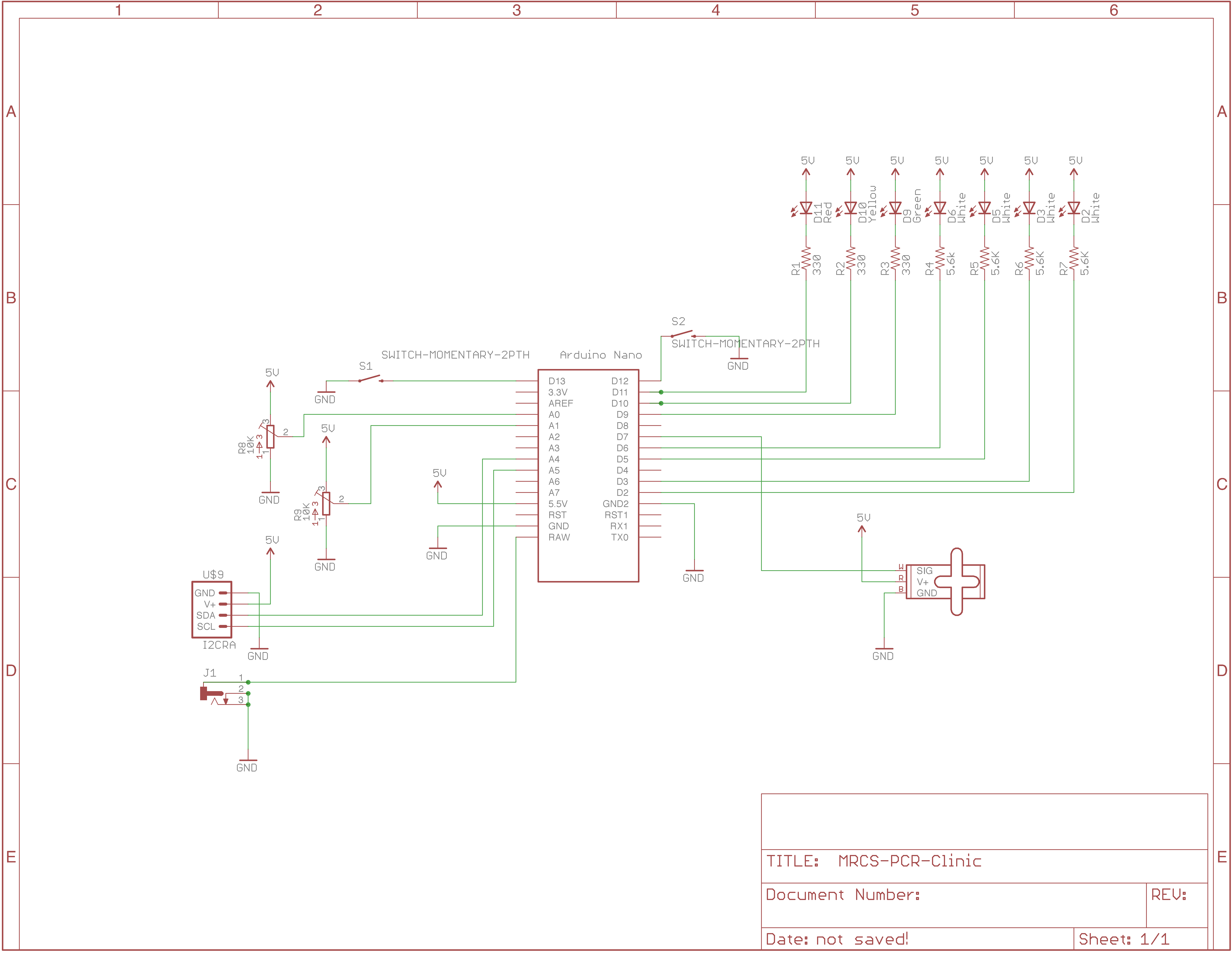
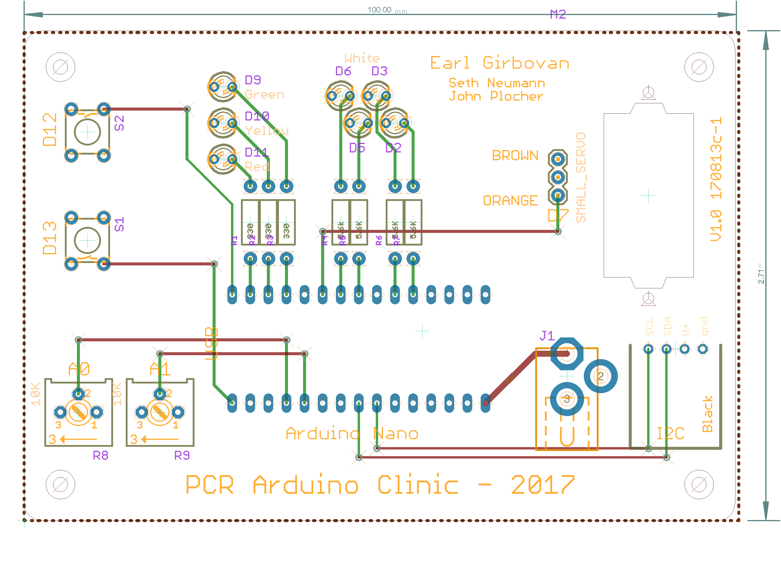
Project board for PCR-NMRA Arduino Programming class by Earl Girbovan and Seth Neumann
The Project Board includes examples of inputs (push buttons, potentiometers) and outputs (LEDs, an SG90 Servo) that are often found in model railroad projects. Since the clinic is about learning the Arduino Integrated Development Environment (IDE) and learning the Arduino “Processing” language, the board is offered assembled so you can start right away without the need to do assembly. Connectors are provided for the Nano (included with the A&T version), external power and ground, and the i/o pins not used on the boards. Pads are provided for an I2C connection if you want to expand your project using our IOX16 and IOX32.
Blink
/* Blink

This program blinks an LED on and off

*/

const int LED2 = 2;  //D2

void setup()
{
  pinMode( LED2, OUTPUT );

}

void loop()
{
  digitalWrite( LED2, HIGH );
  delay( 1000);
  digitalWrite( LED2, LOW );
  delay ( 1000 );

}
Fire_simulator
/* LED Fire Effect
   Uses two amber and one red LED to simulate fire
   From the instructables.com web site, slightly modified
*/

int ledPin1 =  9;
int ledPin2 = 10;
int ledPin3 = 11;

void setup()
{
pinMode(ledPin1, OUTPUT);
pinMode(ledPin2, OUTPUT);
pinMode(ledPin3, OUTPUT);
}

void loop()
{
analogWrite(ledPin1, random(135, 255));
analogWrite(ledPin2, random(135, 255));
analogWrite(ledPin3, random(135, 255));
delay(random(1, 100));
}
GradeCrossing
/*
Grade Crossing

Ties together the blinking lights and servomotor sweep,
along with reading an input, to drive a grade crossing.
The servo simulates a crossing arm.

The sequence is a bit stylized to keep the code manageable
for the clinic.
*/

#include <Servo.h>
Servo Servo1;

int pos;
int MaxPos   = 90;   // max position in degrees
int ServoPos;        // where the servo is in it's sweep
int StepTime = 90;   // time between steps
int ServoTime;       // time since last step

const int TriggerPin = 12;  //Digitial input D12
int Trigger;

int BlinkRate = 1000;  //rate at which the LED blinks
int LEDTime;
int Delta = 90;    // number of msec for each loop iteration
int LEDPin = 2;
boolean LEDState;

void setup()
{
  pinMode( TriggerPin, INPUT_PULLUP);
  //tell the Arduino & the servo driver that the servo is connected to pin 7
  Servo1.attach(7);
  Servo1.write( 0 );   // ensure the crossing gate is raised
  ServoPos = 0;
  LEDState = false;    // LED starts off
  pinMode ( LEDPin, OUTPUT );
  digitalWrite ( LEDPin, HIGH );
  } // end of setup

void loop()
{
  //poll, looking for a LOW to start the sequence
  do
  {
    Trigger = digitalRead( TriggerPin );
  }
  while( Trigger == HIGH );

  //start the sequence
  ServoTime  = StepTime;   // initialize the crossing arm timer
  LEDTime    = 0;          // go into the routine with the LED off, so it will turn on
  LEDState   = false;
  ServoPos   = 0;         // crossing arm raised position
  do
    {
    // see if we need to change the stat of the LED
    LEDTime = LEDTime - Delta;
    if( LEDTime <= 0 )
      {
        LEDState = !LEDState;  //LED to other state; on or off
        if (LEDState)
        {
          digitalWrite ( LEDPin, LOW );
        }
        else
        {
          digitalWrite ( LEDPin, HIGH );
        }
        LEDTime = BlinkRate;  //load up the next blink cycle
      }

    //see if we need to change the state of the crossing arm
    ServoTime = ServoTime - Delta;
    if( ServoTime <= 0 )
      {
        //if arm not at down position, move it
        if( ServoPos < MaxPos )
          {
            ServoPos++;
            Servo1.write( ServoPos );
            // and reset the timer for the next step
            ServoTime = StepTime;
          }
      }
    delay ( Delta );
    Trigger = digitalRead( TriggerPin );
    }
  while ( Trigger == LOW );

  //switch has been released, turn off the light and raise the arm
  digitalWrite( LEDPin, HIGH );

  for( int pos = ServoPos; pos >=1; pos--)
  {
    Servo1.write(pos);
    delay( StepTime );
  }


} // end of loop
GradeCrossing_2_ino
/*
Grade Crossing

Ties together the blinking lights and servomotor sweep,
along with reading an input, to drive a grade crossing.
The servo simulates a crossing arm.

The sequence is a bit stylized to keep the code manageable
for the clinic.
*/

#include <Servo.h>
Servo Servo1;

int pos;
int MaxPos   = 90;   // max position in degrees
int ServoPos;        // where the servo is in it's sweep
int StepTime = 90;   // time between steps
int ServoTime;       // time since last step

const int TriggerPin = 12;  //Digitial input D12
int Trigger;

int BlinkRate = 1000;  //rate at which the LED blinks
int LEDTime;
int Delta = 90;    // number of msec for each loop iteration
int LEDPin = 2;
boolean LEDState;

void setup()
{
  pinMode( Triggerpin, INPUT_PULLUP);
  //tell the Arduino & the servo driver that the servo is connected to pin 7
  Servo1.attach(7);
  Servo1.write( 0 );   // ensure the crossing gate is raised
  ServoPos = 0;
  LEDState = false;    // LED starts off
  pinMode ( LEDPin, OUTPUT );
  digitalWrite ( LEDPin, HIGH );
  } // end of setup

void loop()
{
  //poll, looking for a LOW to start the sequence
  do
  {
    Trigger = digitalRead( TriggerPin );
  }
  while( Trigger == HIGH );

  //start the sequence
  ServoTime  = StepTime;   // initialize the crossing arm timer
  LEDTime    = 0;          // go into the routine with the LED off, so it will turn on
  LEDState   = false;
  ServoPos   = 0;         // crossing arm raised position
  do
    {
    // see if we need to change the stat of the LED
    LEDTime = LEDTime - Delta;
    if( LEDTime <= 0 )
      {
        LEDState = !LEDState;  //LED to other state; on or off
        if (LEDState)
        {
          digitalWrite ( LEDPin, LOW );
        }
        else
        {
          digitalWrite ( LEDPin, HIGH );

        LEDTime = BlinkRate;  //load up the next blink cycle
      }

    //see if we need to change the state of the crossing arm
    ServoTime = ServoTime - Delta;
    if( ServoTime <= 0 )
      {
        //if arm not at down position, move it
        if( ServoPos < MaxPos )
          {
            ServoPos++;
            Servo1.write( ServoPos );
            // and reset the timer for the next step
            ServoTime = StepTime;
          }
      }
    delay ( Delta );
    Trigger = digitalRead( TriggerPin );
    }
  while ( Trigger = LOW );

  //switch has been released, turn off the light and raise the arm
  digitalWrite( LEDPin, HIGH );

  for( int pos = ServoPos; pos >=1; pos--)
  {
    Servo1.write(pos);
    delay( StepTime );
  }


} // end of loop
Intermittent_Fire_simulator
/* LED Fire Effect
   Uses two amber and one red LED to simulate fire
   From the instructables.com web site

   Included a WHILE loop, so that the effect turns on and off.
*/

int ledPin1 =  9;
int ledPin2 = 10;
int ledPin3 = 11;
int OnTime;
int OffTime;
int i;

void setup()
{
pinMode(ledPin1, OUTPUT);
pinMode(ledPin2, OUTPUT);
pinMode(ledPin3, OUTPUT);
}

void loop()
{
OnTime = random( 1000, 5000 );
while( OnTime > 0 )
  {
  analogWrite(ledPin1, random(120)+135);
  analogWrite(ledPin2, random(120)+135);
  analogWrite(ledPin3, random(120)+135);
  i = random(1, 100);
  delay( i );
  OnTime = OnTime - i;
  }

  // off time, ensure the LEDs are turned off
  analogWrite(ledPin1, 255 );
  analogWrite(ledPin2, 255 );
  analogWrite(ledPin3, 255 );
  OffTime = random ( 1000, 3000 );
  delay ( OffTime );
}
PCR_test_and_demo
/*

    servo Sweep is by BARRAGAN <http://barraganstudio.com>
    This example code is in the public domain.

     modified 8 Nov 2013
     by Scott Fitzgerald
     http://arduino.cc/en/Tutorial/Sweep

*/

#include <Servo.h>


// LED setup
#define LED2 2     // LED no PWM
#define LED3 3     // LEDs PWM
#define LED5 5     // LEDs PWM
#define LED6 6     // LEDs PWM
#define LED9  9
#define LED10 10
#define LED11 11
// push button for LED 9
#define BUTTON 12

#define SERVO_PIN  7


#define MAX 255 // PWM maximum
#define MID  96 // PWM mid point, not really but more visible
#define MIN   0 // PWM minimum
#define TICK 10 // clock tick

Servo myservo;  // create servo object to control a servo
                // twelve servo objects can be created on most boards

int pos = 0;    // variable to store the servo position

int buttonval = 0; // for push button test -- lites LED 9
int pot0val = 0; // for pot 0, lites LED 10
int pot1val = 0; // for pot 1, lites LED 11


void setup() {
    myservo.attach(SERVO_PIN);  // attaches the servo on pin 7 to the servo object

    pinMode(LED9, OUTPUT);
    pinMode(LED10, OUTPUT);
    pinMode(LED11, OUTPUT);
    pinMode(BUTTON, INPUT_PULLUP);
}

void loop() {
    for (byte i = 0; i < 255; i++){
	analogWrite(LED2, i);
	analogWrite(LED3, i);
	analogWrite(LED5, i);
	analogWrite(LED6, i);

	delay (TICK);
    }
    delay (1000);

    // analogWrite(LED2, MAX);   // turns the LED on
    // analogWrite(LED3, MAX);   // turns the LED on
    // analogWrite(LED5, MAX);   // turns the LED on
    // analogWrite(LED6, MAX);   // turns the LED on

    // delay(TICK);             // waits for a second
    // analogWrite(LED2, MID);   // turns the LED on halfway
    // analogWrite(LED3, MID);   // turns the LED on halfway
    // analogWrite(LED5, MID);   // turns the LED on halfway
    // analogWrite(LED6, MID);   // turns the LED on halfway

    // delay(TICK);             // waits for a second

    // analogWrite(LED2, MIN);   // turns the LED off
    // analogWrite(LED3, MIN);   // turns the LED off
    // analogWrite(LED5, MIN);   // turns the LED off
    // analogWrite(LED6, MIN);   // turns the LED off

    //delay(TICK);             // waits for a second

    // push button

    buttonval = digitalRead(BUTTON); // push button, only reads once through cycle
    if (buttonval == LOW){
	digitalWrite (LED9,LOW);
    } else {
	digitalWrite (LED9,HIGH);
    }

    pot0val = analogRead (0); // first pot
    analogWrite (LED10, pot0val/4); // scale the 1024 bit input to 256 bit output
    pot1val = analogRead (1); // first pot
    analogWrite (LED11, pot1val/4); // scale the 1024 bit input to 256 bit output

    delay (10);

    // from Banzi example 6B
    for(pos = 0; pos <= 180; pos += 1) // goes from 0 degrees to 180 degrees
    {                                  // in steps of 1 degree
	myservo.write(pos);              // tell servo to go to position in variable 'pos'
	delay(15);                       // waits 15ms for the servo to reach the position
    }

    for(pos = 180; pos>=0; pos-=1)     // goes from 180 degrees to 0 degrees
    {
	myservo.write(pos);              // tell servo to go to position in variable 'pos'
	delay(15);                       // waits 15ms for the servo to reach the position
    }
}
Sweep_servo
/*
Servo Sweep

This program slowly sweeps a servo back and forth from 0 to a presettable maximum number of degrees.
*/

#include <Servo.h>

Servo Servo1;

int pos;
int MaxPos = 90;
int DelayTime = 90;

void setup()
{
  //tell the Arduino & the servo driver that the servo is connected to pin 7
  Servo1.attach(7);
}

void loop()
{
  //sweep the servo back and forth
  for( pos = 1; pos <=MaxPos; pos++ ) //sweep from 0 to MaxPos in 1 degree steps
  {
    Servo1.write(pos);
    delay(DelayTime);
  }
  delay( 1000 );

  //now sweep it back
  for( pos = MaxPos; pos >=1; pos--)  //sweep from MaxPos to 0 in 1 degree steps
  {
    Servo1.write(pos);
    delay(DelayTime);
  }
  delay( 1000 );
}
doc
Project board for PCR-NMRA Arduino Programming class by Earl Girbovan and Seth Neumann
The Project Board includes examples of inputs (push buttons, potentiometers) and outputs (LEDs, an SG90 Servo) that are often found in model railroad projects. Since the clinic is about learning the Arduino Integrated Development Environment (IDE) and learning the Arduino “Processing” language, the board is offered assembled so you can start right away without the need to do assembly. Connectors are provided for the Nano (included with the A&T version), external power and ground, and the i/o pins not used on the boards. Pads are provided for an I2C connection if you want to expand your project using our IOX16 and IOX32.
servo_with_travel_set_by_pots
#include <Servo.h> // servo Sweep is by BARRAGAN <http://barraganstudio.com> This example code is in the public domain.
Servo myservo;     // create servo object to control a servo
                   // twelve servo objects can be created on most boards

int pos;

//const int LED9 = 9; PWM functionality diabled by using servo library
//const int LED10 = 10; PWM functionality diabled by using servo library

int pot0val = 0; // value for pot read
int pot1val = 0; // value for pot read
int lowpos = 1;  // set it in the range of servo
int highpos = 127;// set it in the range of servo

void setup() {

myservo.attach(7);  // attaches the servo on pin 7 to the servo object

//byte i;
}

void loop() {

 pot0val = analogRead (0); // first pot
 lowpos = pot0val/6; //scale to 1-~180, this is actually 170 degrees
 pot1val = analogRead (1); // second pot
 highpos = pot1val/6; //scale to 1-~180
 {for ( pos=lowpos; pos<=highpos; pos++){

    myservo.write(pos);              // tell servo to go to POSition
    delay(20);                       // waits 15ms for the servo to reach the position
  }
 delay(500); // time to recyle
  }

 // from Banzi example 6B
}
This technical documentation is licensed under the Creative Commons Attribution-NonCommercial-ShareAlike