IO4-QuadOD
IO4 Quad Detector for DCCOD and CPod detector cards - hardwired, IO4 or WeMos/WiFi connected
An IO4 peripheral baseboard for Chubb-style current sensing detectors.
|
IO4-QuadOD Version 2.0
First built: 2018-11
An IO4 peripheral baseboard for Chubb-style current sensing detectors.
|
|
|
UNPUBLISHED
Documentation
Description
This project is a simple baseboard for current sensing detectors. It was inspired (in reverse chronological order) by railnerd, MarkS, MRCS, RR-Cirkits and, of course, Dr Bruce Chubb.
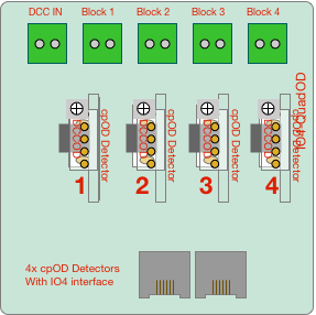
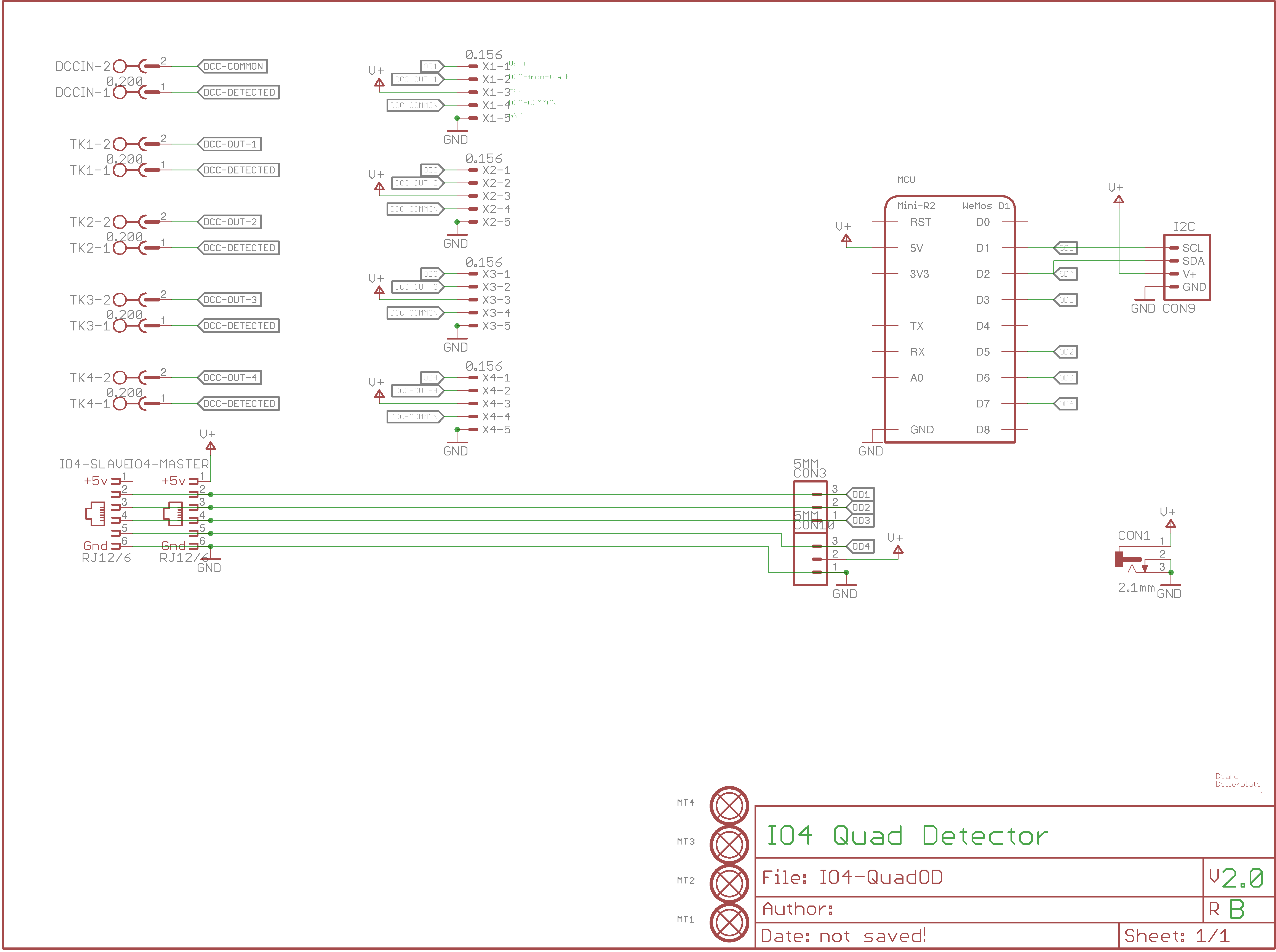
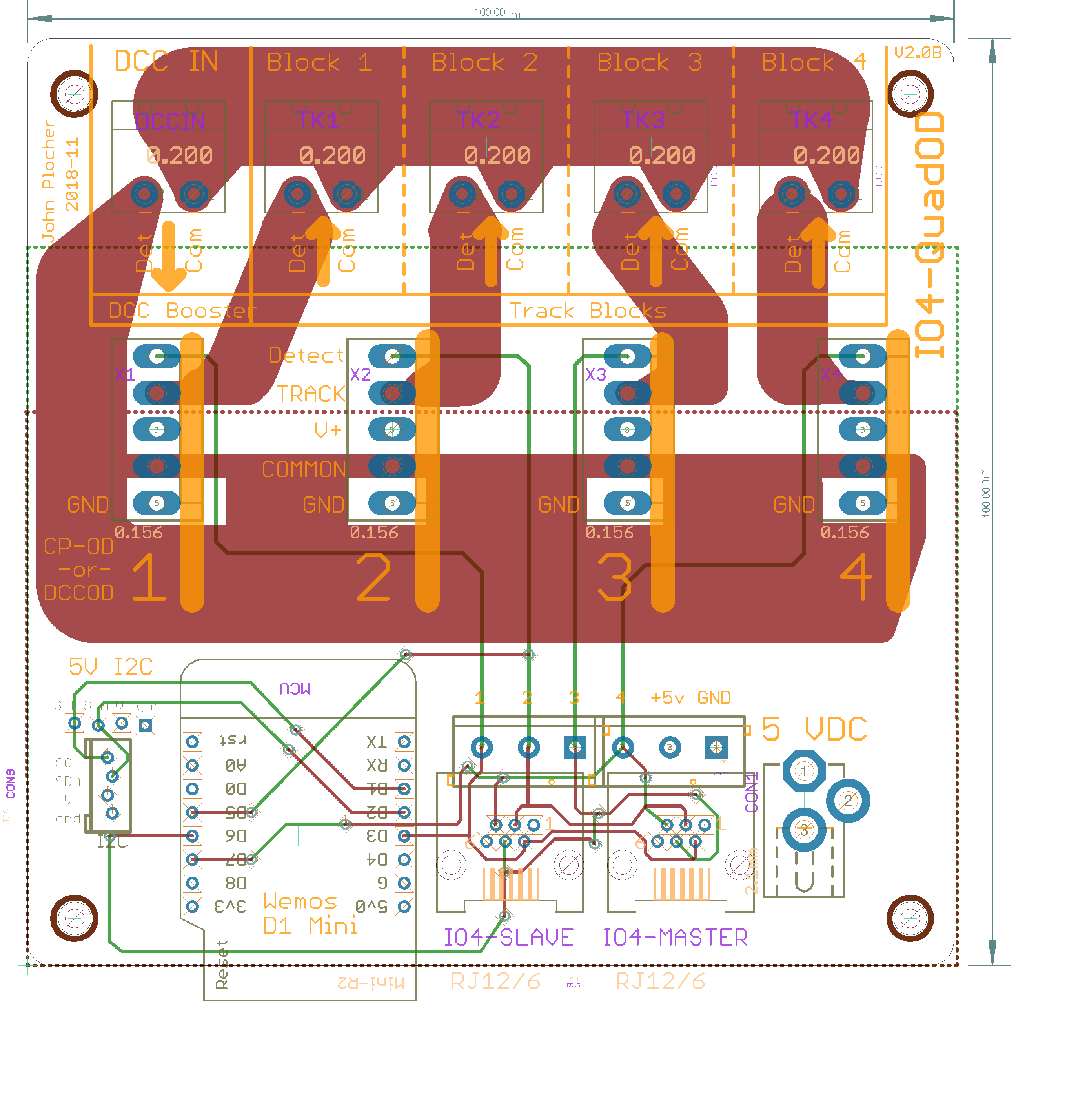
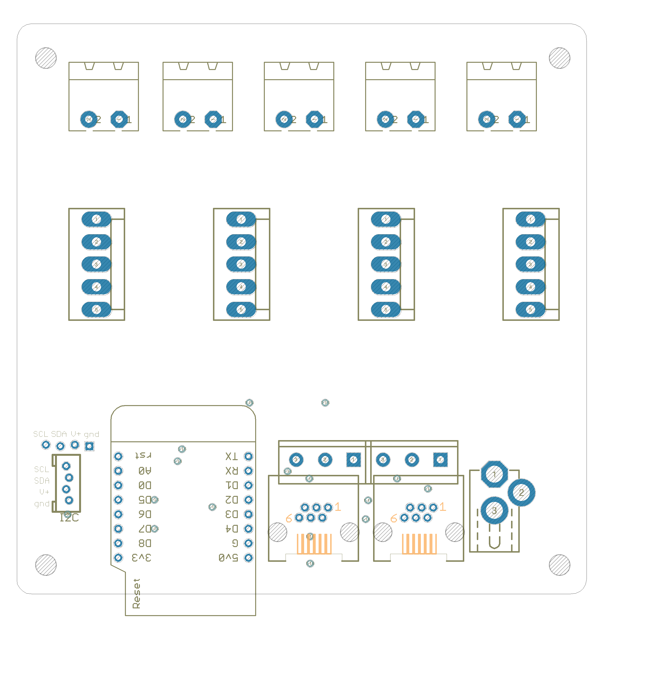
The Quad-OD board has 4x connectors that can be populated with either MRCS cpOD or CMRI DCCOD occupancy detector cards. The board can be powered locally (with a +5vDC wall wart) or remotely (by a “IO4 Field Unit” I/O card), and provides 4x open drain “pull to ground when detected” occupancy feedback lines.
The IO4-QuadOD is a multi-purpose board - it supports 3 different use cases:
- It can be an IO4 peripheral using the SPCoast 6-pin RJ12 connector scheme,
- It can be hardwired using screw terminals and/or a 5VDC wallwart, or
- With the addition of a WemosD1Mini 8266 MCU board, it can become a distributed WiFi and/or I2C peripheral. (Software not provided…)
THere were several previous versions:
- Rev 1.0 was a conceptual effort to build a self contained unit (like the [[IO4-Detector]], but with DCC-OD design instead of a Paisley one) but the complexity and inflexability doomed it…
- Rev 2.0A simplified things to simply use DCC-OD style cards AS-IS. Unfortunately, the card-to-card spacing was a bit too tight, and 4x cards wouldn’t fit without severely distorting the PCB.
- Rev 2.0B is the same design as 2.0A, but with fixed spacing.
The 2x IO4 connections are arranged so that two adjacent control points can both monitor a shared set of detected blocks (usually used by approach logic…). One (master) provides a power source, the other (slave) does not; all other signals from the IO4 connector are in common. This implies that both need to be connected to INPUT configured ports.
This technical documentation is licensed under the CERN Open Hardware Licence v1.2