IO4-DCC-Booster
IO4 DCC Booster
A DIY DCC booster for a BOM cost of about $20 when using bulk China/eBay parts.
I was working on designing a motor shield using the $10 IBT-2 H-Bridge when I came across the work done by D. Bodnar at [train electronics.com](http://www.trainelectronics.com/DCC_Arduino/DCC_Booster/)
I wanted to use one of these for every control point on my layout instead of a DCC circuit breaker + booster power district mashup. As the DCC Breakers are at least double the DIY cost for these dedicated boosters, and I will end up with 10-20 control points on my SPCoast layout, the savings might actually cover the development costs :-)
These boosters DO NOT support auto-reverse, and the sketch software doesn't try to do soft start detection of sound decoder capacitor inrush currents. Since there will be on average a single train powered by each of these boosters on my N-Scale layout, I don't expect this to be a real issue. In practice, a simple 1 or 2 amp unit would probably be good enough; at 5 to 6 amps, this is overkill. From Bedner's original web writeup at trainelectronics.com:
Introduction
In addition to experimenting with DCC++ over the last few months I have been trying out different H-Bridges to see if there is one that would work with DCC++ while delivering more than the 1 to 2 amps that the standard Arduino Motor Shield provides. Such a option would a good option for G scale layouts that typically draw much more power than smaller scales.
I came across a few higher power shields that are described here including one that has an advertised power capability of 43 amps. While I am a bit skeptical about this claim my tests show that it has no problem delivering 5 or more amps, more than enough for my purposes. I describe how this can be interfaced to the DCC++ controller in the link above.
In order to make the use of this H-Bridge more convenient I decided to design a stand-alone DCC booster that would attach to a DCC signal and boost it before powering a track. The booster is designed to work with DCC++, Digitrax and other systems.
Hardware - H-Bridge
The H-Bridge is available from eBay, Amazon and other vendors - just search for "H-Bridge 43 amp BTS7960B". Make sure you get the unit that has two BTS7960B devices on it - each is 1/2 of an H-Bridge. The control signals go to the 8 pins on the front and the power in and power out wires go to the 4 pin screw terminal connector at the rear.
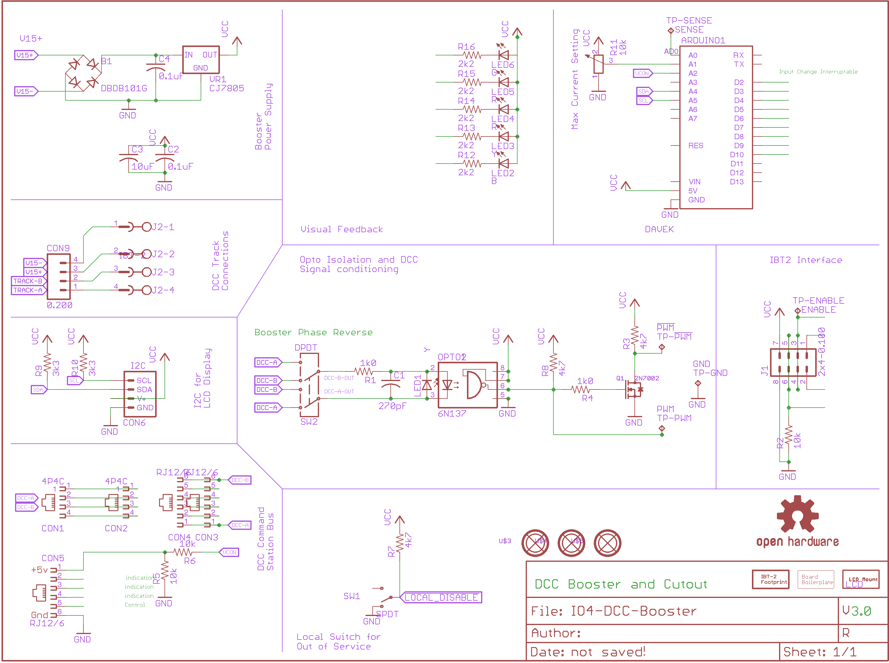
This H-Bridge and similar units do not operate on the single PWM signal that most DCC systems provide. It needs a right hand rotating PWM and a left hand PWM. To change the single PWM signal to two a simple one transistor circuit is needed. That circuit can be seen in the lower left corner of the schematic (below).
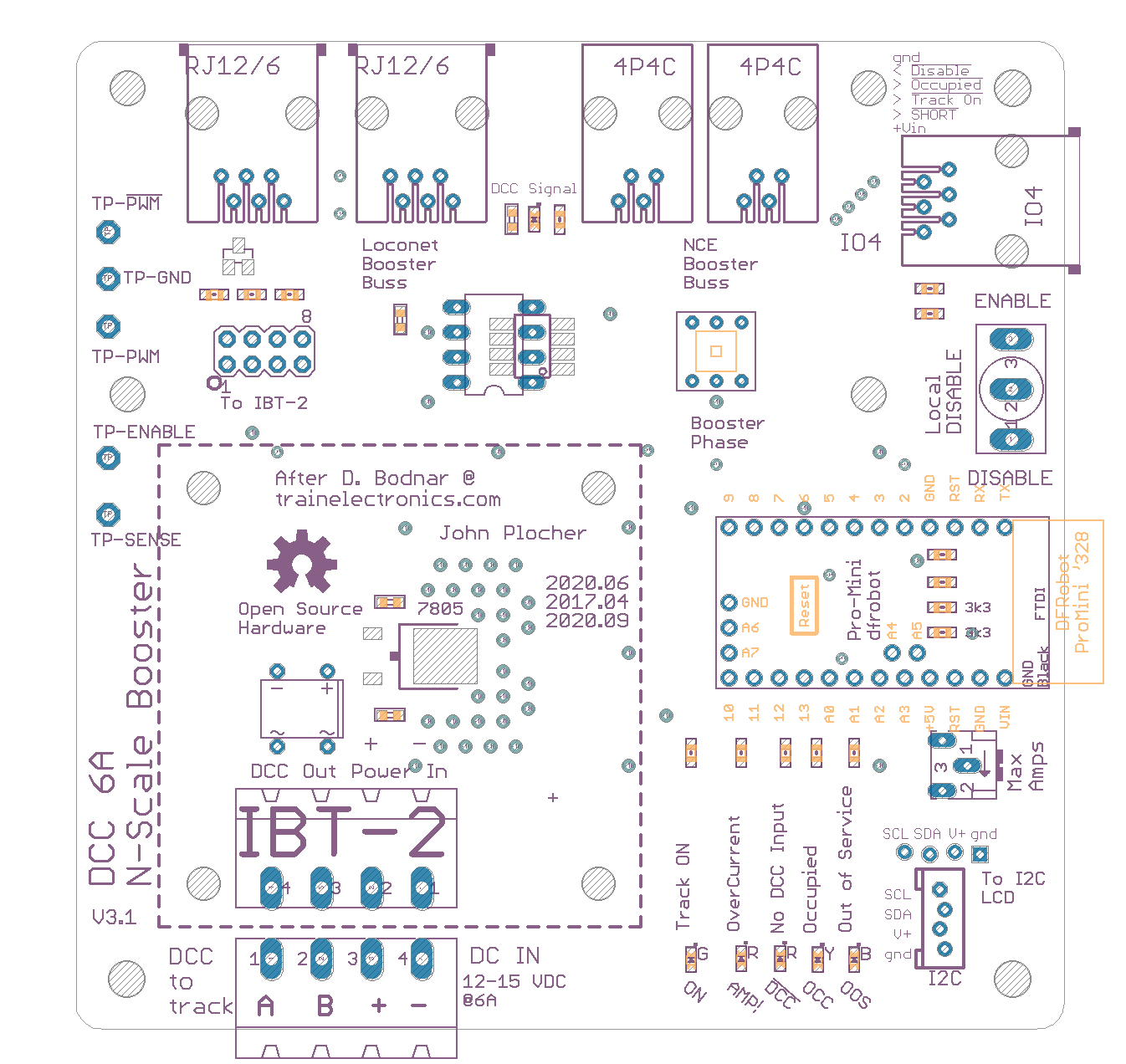
The H-Bridge can act as a DCC booster without much more than the Opto Coupler circuit and the one transistor converter. The H-Bridge does hove an over current shutdown capability but it doesn't react until well over 30 amps are being drawn, way more than we are going to use. To get around this problem so that the system shuts down immediately if the track is shorted an Arduino Pro Mini has been added. The Arduino monitors the current sensing pin on the H-Bridge and can turn it off should it detect a high reading. </blockquote> Their prototype reused a board he had on hand; this project simply turns their schematic into a purpose-built board - and adds remote control (enable/disable and monitoring) via an IO-4 RJ12/6 interface. My differences: * powered by the DC booster power. * local control - a maintainer "disable track power" switch * remote control via IO4 connector * enable/disable track power * remote feedback via IO4 connector * enabled * occupied * overload * Loconet and NCE Booster Bus daisy chain command station cable jacks === Estimated BOM costs ===
	$ 1.00  PCB
	$10.00  IBT-2
	$ 3.50  Pro Mini Clone
	$ 0.45  6n137
	$ 0.20  2200uF x2
	$ 3.00  RJ and Phoenix connectors
	$ 1.00  SPDT Switch
	$ 1.00  R/C/LEDs
	------
    ~$20.00
The booster uses an external 12-18v 6A+ DC power supply; the logic and feedback electronics are isolated from the power supply (using opto isolator for the booster bus and a full wave bridge for the power supply), so there should be no problems driving a set of boosters from a single large amperage switching supply. As with ALL high power systems, use a SLOW BLOW or POLYFUSE in your power supply feed. 20v at 6A is 120W - similar to a very bright and hot incandescent bulb, if you remember them. You don't want to arc weld or start a fire on your layout if something goes wrong!
|
IO4-DCC-Booster Version 3.1
First built: 2017.04
- 1.0 - initial version - proof of concept - numerous "errors" and limitations
- 2.0 - Miswired AC power feed, shorted out via a missed/unwanted ground trace
- 3.0 - Working version powered via IO4 connection
- 3.1 - Powered via DC Power Supply </ul
|
|
|

Download IO4-DCC-Booster.gerbers.zip - Gerber Fabrication files
Download IO4-DCC-Booster.parts - Parts List (spreadsheet data)
IO4-DCC-Booster.bom
| Parts | Value | Package | Quantity | Library | Type/Feeder |
|---|---|---|---|---|---|
| C2, C4 | 0.1uF | 0603-CAP | 2x | SPCoast | 19 |
| CON9 | 0.200 | MSTBA4 | 1x | SPCoast | PTH |
| R1, R4 | 1k0 | 0603-RES | 2x | SPCoast | 41 |
| R12, R13, R14, R15, R16 | 2k2 | 0603-RES | 5x | SPCoast | 42 |
| Q1 | 2N7002 | SOT23 | 1x | SPCoast | NONE |
| J1 | 2x4-0.100 | MA04-2 | 1x | con-lstb | PTH |
| R9, R10 | 3k3 | 0603-RES | 2x | SPCoast | 43 |
| R3, R7, R8 | 4k7 | 0603-RES | 3x | SPCoast | NONE |
| CON1, CON2 | 4P4C | 555980-1 | 2x | SPCoast | PTH |
| OPTO1 | 6N137 | DIL08 | 1x | SPCoast | PTH |
| OPTO2 | 6N137 | SM8 | 1x | SPCoast | NONE |
| R2, R5, R6 | 10k | 0603-RES | 3x | SPCoast | 46 |
| R11 | 10k | B25X | 1x | SPCoast | PTH |
| C3 | 10uF | 0603-CAP | 1x | SPCoast | 22 |
| C1 | 270pF | 0603-CAP | 1x | SPCoast | NONE |
| LED2 | B | 0603-LED | 1x | SPCoast | 4 |
| BOARD1 | BOARD | BOARD-SEEED10X10-NOHOLES | 1x | SPCoast | PTH |
| VR1 | CJ7805 | TO-252 | 1x | SPCoast | NONE |
| ARDUINO1 | DAVEK | ARDUINO_PRO_MINI_DAVEK | 1x | SPCoast | PTH |
| B1 | DBDB101G | DB | 1x | SPCoast | PTH |
| SW2 | DPDT | 8X8-SQ-PB | 1x | SPCoast | PTH |
| LED6 | G | 0603-LED | 1x | SPCoast | 3 |
| CON6 | I2C | I2C-L | 1x | SPCoast | PTH |
| U$2 | IBT-2 | IBT-2 | 1x | SPCoast | PTH |
| J2 | IBT-2 | MSTBA4 | 1x | con-phoenix-508 | PTH |
| LCD | LCD | LCD-16X2-SILK | 1x | SPCoast | PTH |
| U$3, U$4, U$5 | MOUNTINGHOLE | MOUNTINGHOLE | 3x | SPCoast | PTH |
| LOGO1 | OSHW | OSHW-LOGO-L | 1x | SPCoast | PTH |
| LED4, LED5 | R | 0603-LED | 2x | SPCoast | 1 |
| CON3, CON4, CON5 | RJ12/6 | RJ25-PANEL | 3x | SPCoast | PTH |
| SW1 | SPDT | SWITCH-SPDT-508 | 1x | SPCoast | PTH |
| TP-!PWM, TP-ENABLE, TP-GND, TP-PWM, TP-SENSE | TPPAD1-13 | P1-13 | 5x | testpad | PTH |
| LED1, LED3 | Y | 0603-LED | 2x | SPCoast | 2 |
This technical documentation is licensed under the CERN Open Hardware Licence v1.2