I2C-8574
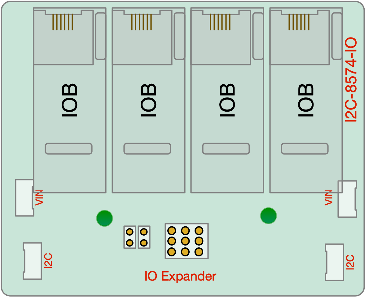
I2C PCF8474-based IO Expander with 4x IOB daughterboard connections
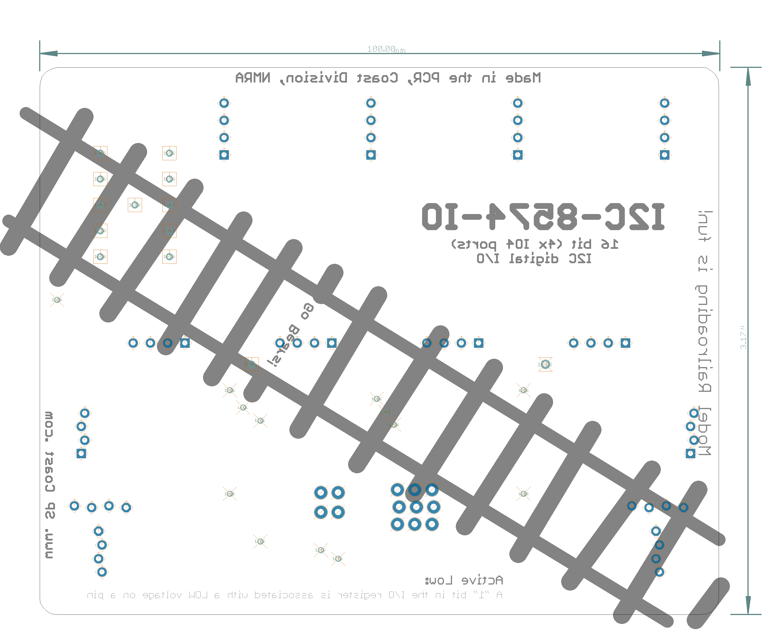
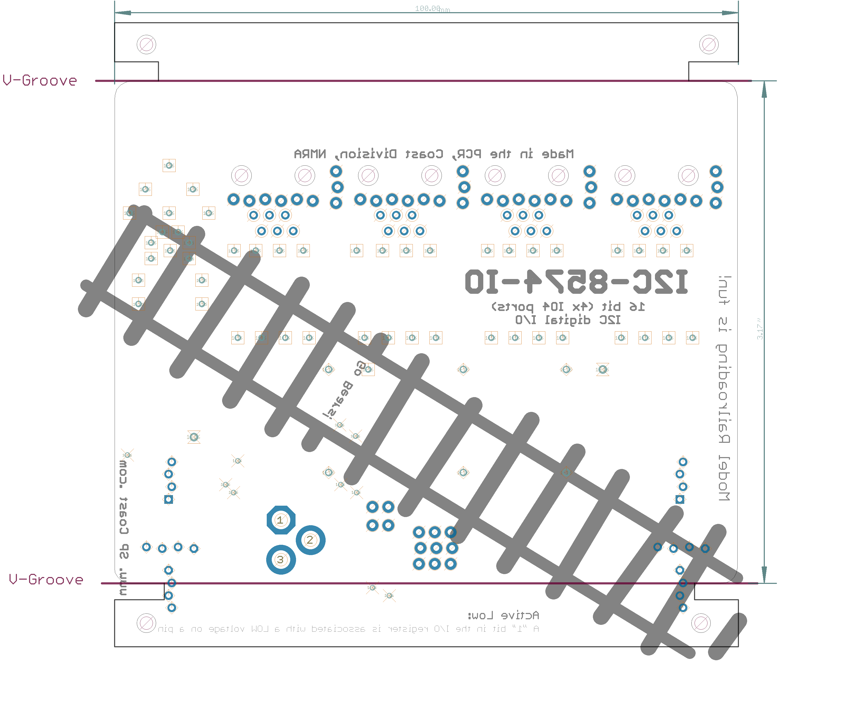
- 4x IOB daughterboard connections * 3.17” Tyco rail size
|
Download I2C-8574 -
Download PCF8574.pdf - Documentation
Download PCF8574A.pdf - Documentation
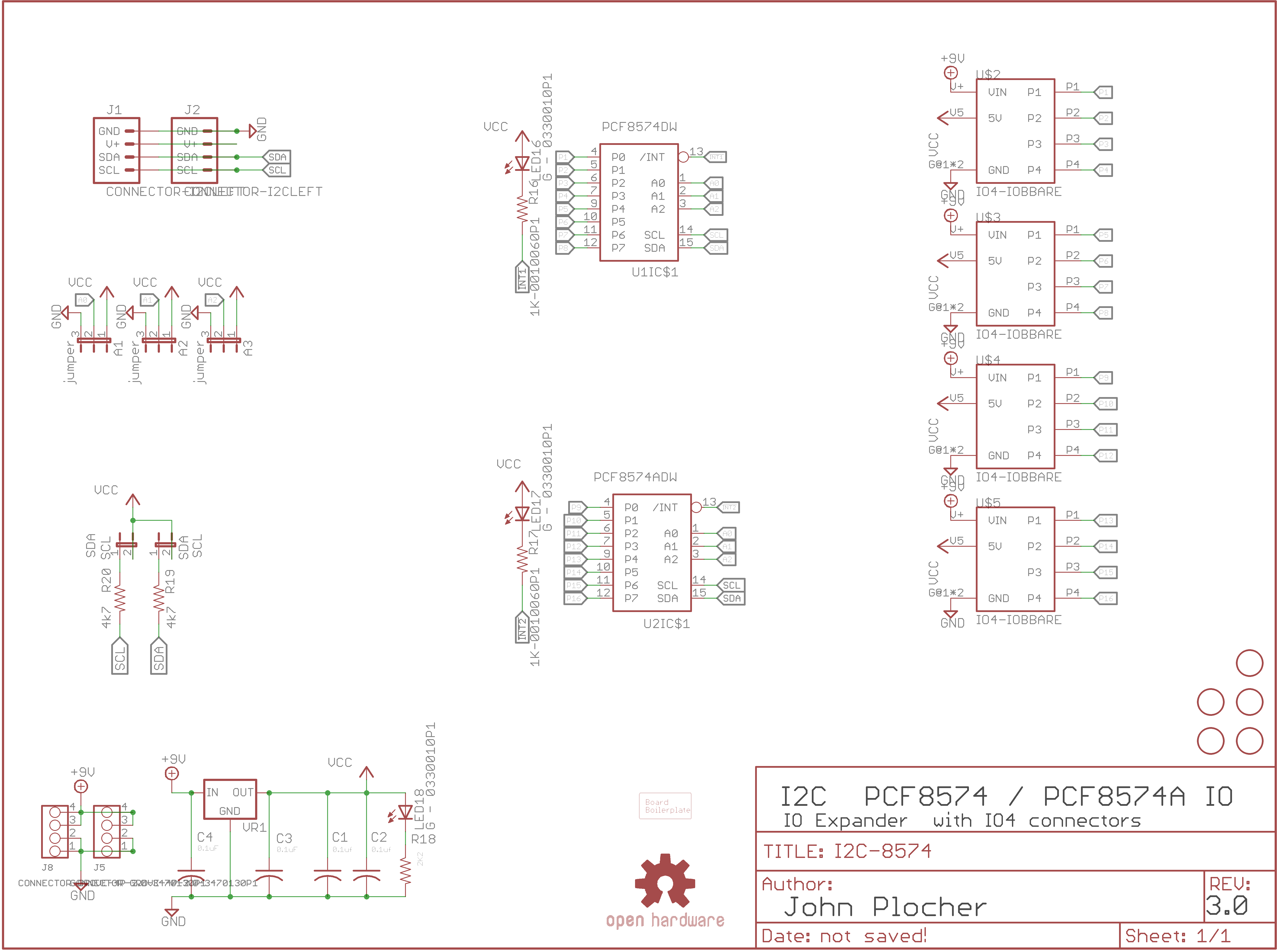
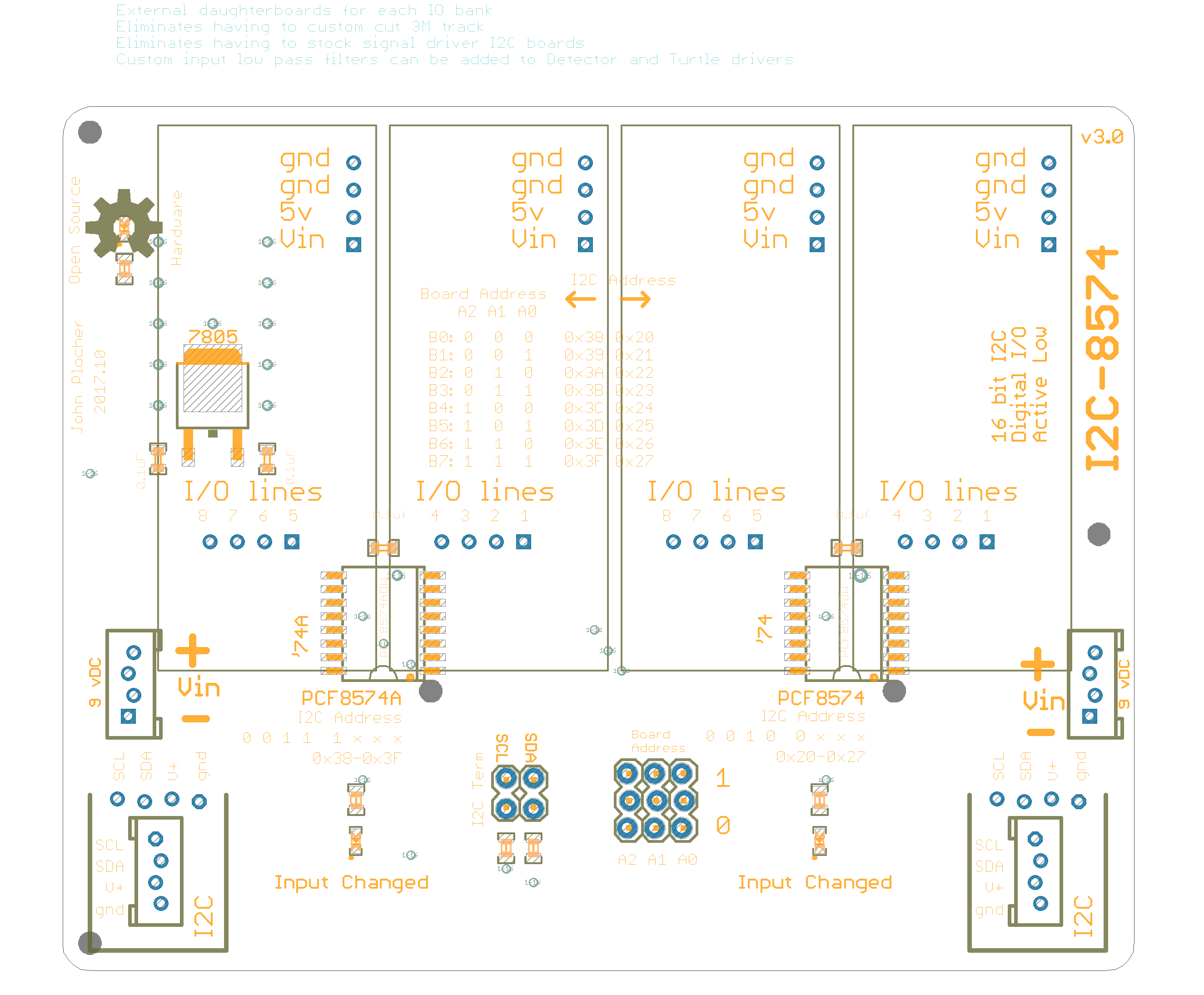
I2C-8574 Version 3.0
First built: 2017-10
- 4x IOB daughterboard connections * 3.17” Tyco rail size
|
|
|
UNPUBLISHED
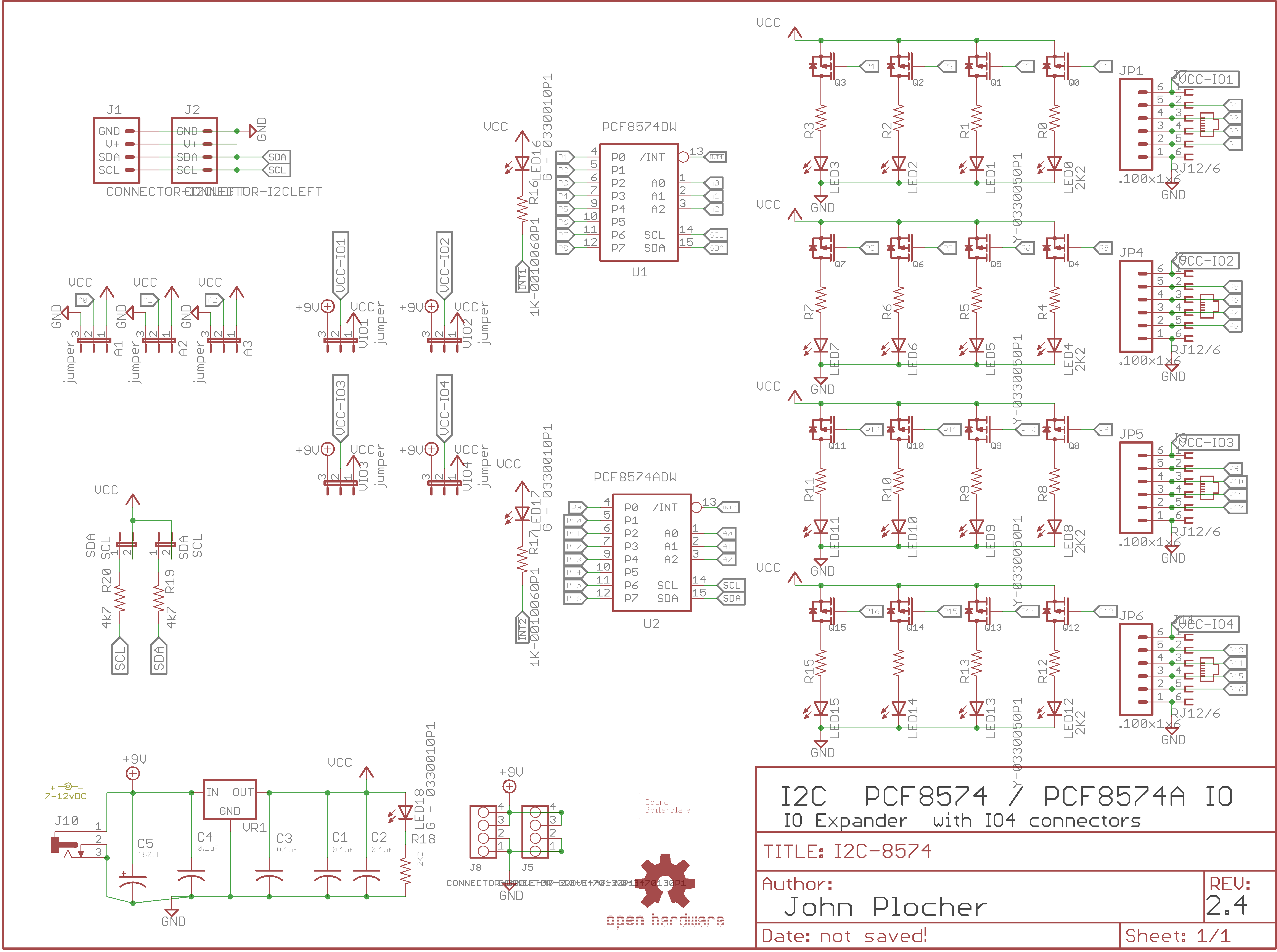
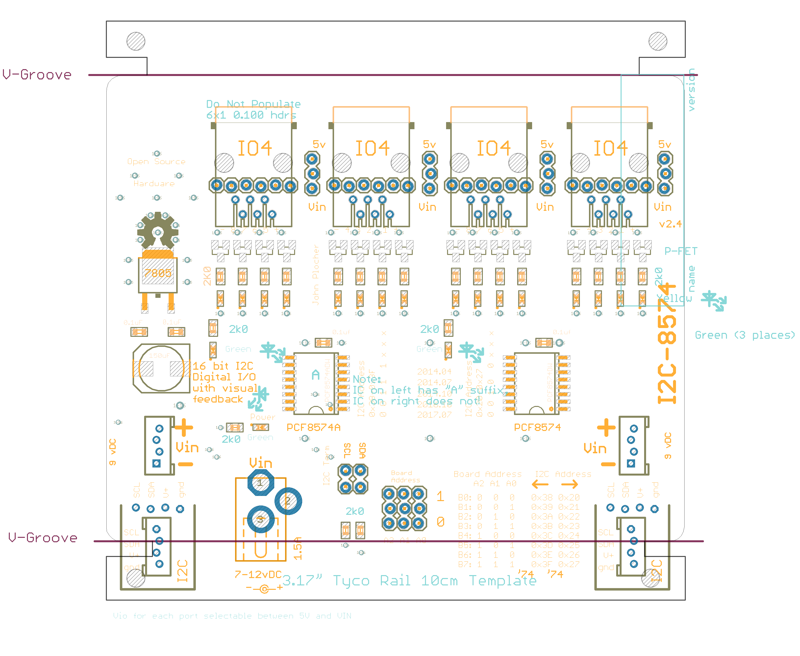
I2C-8574 Version 2.4
First built: 2014-04, 2014-07, 2014-10, 2016-10, 2017-11
- 4x IO4 connections * RJ12 or 0.100 pin termination on each IO4 location * per-IO4-port 12v/5v selection * 3.17” Tyco rail size
|
|
|

UNPUBLISHED
Documentation
Introduction
This board was originally produced to help me build control panels for my model railroad - I needed to connect many different buttons, switches and lights to an Arduino, and also connect the Arduino to a communications bus (Ethernet, CAN or Loconet), and I couldn't find anything that had both high IO point density AND visual feedback.
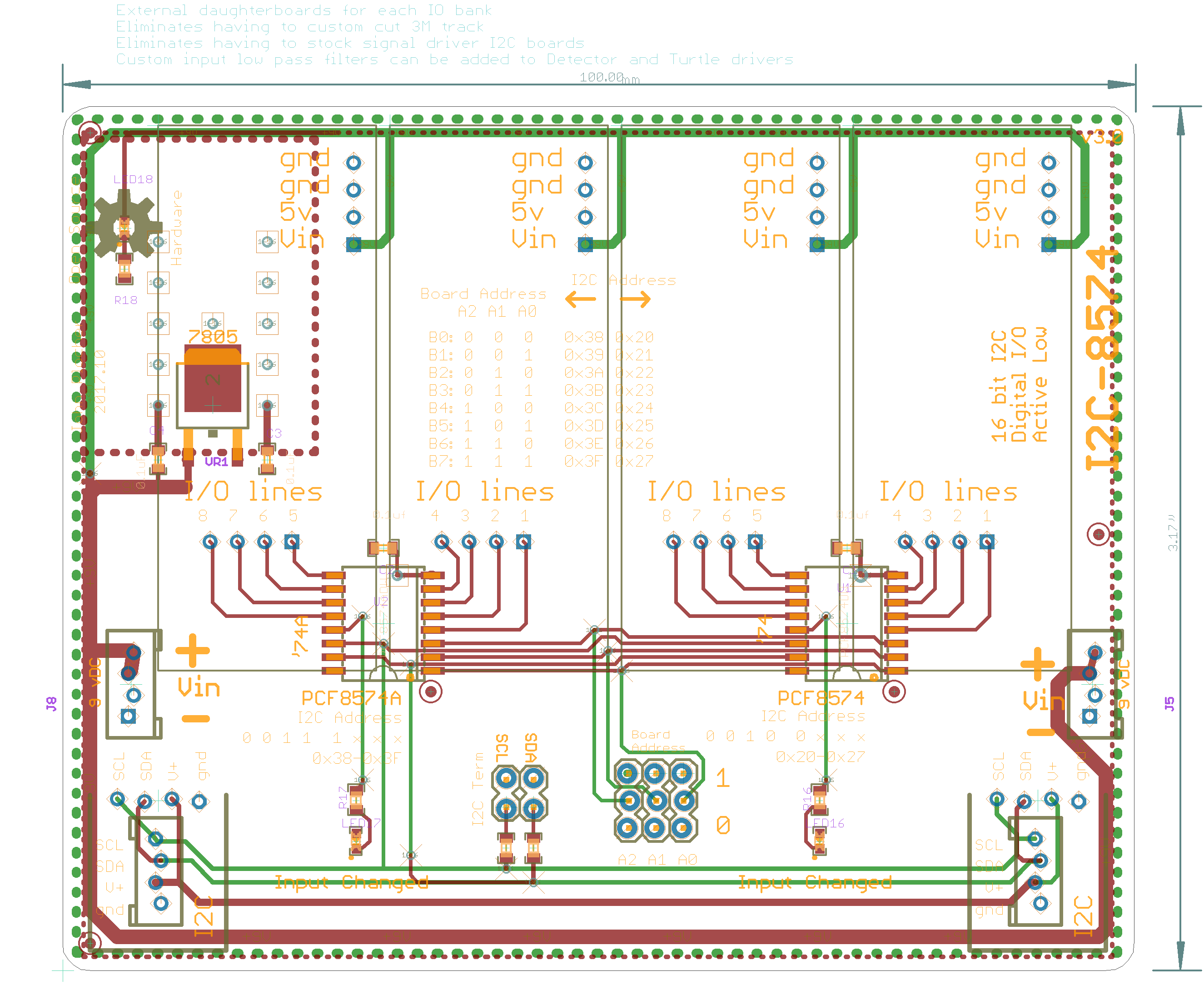
I started with a simple Arduino ShowMeShield with Active-Low monitoring LEDs on each pin. I quickly iterated (understatement) through at least a dozen designs, trying to discern what worked well and what didn't. I'll spare you the details… I was aiming to support up to the max I2C devices that can be used together; for the PCF8474 series, that would be 8x devices of each type, for a total of 16x8, or 128 i/o points.
(Active-LOW means that the LOGICAL “ON” state is when the PHYSICAL state is low. In this case, the indication LED is on when the desired pin is grounded; when programming, writing a "1" to an Active Low port will cause it to ground).
Cautions
With several hundred IO loads, and up to 32 external breakout devices, a suitable power supply needs to be used.
In practice, a 2A 9-12VDC supply a good choice.
This supply needs to power the Arduino, its direct IO loads, the I2C expander chain AND provide ~100mA to each IO4 device. Instead of relying on the Arduino's onboard regulated supply (which is only good for about 100mA itself), each board has its own regulator, and there is a common supply feed that can handle about 2.5A @ 12v. If more power is needed, the daisy chained power feed thru can be replaced with a per-board independent supply.
Specifications
This IO board is based on the 8574 I2C 8-bit IO Expander, with a buffered LED driver (discrete P-FETs) connected to a bank of LEDs that show the status of the I/O lines in real time.
Each board provides a latched set of 16x IO points, with each point being software selectable to be either an input or an output. The individual points are reasonably protected from the environment, and can easily drive or sink 10 mA each. By using active low inputs and outputs, the effects of environmental noise are reduced - remote sensors only need to ground an I/O point to register activity.
Communication Protocol
Simple I2C Reads and Writes:
int I2Cextender::read8(int i2caddr) {
    int _data = -1;
    Wire.requestFrom(i2caddr, 1);
    if(Wire.available()) {
      _data = Wire.receive();
    }
    return _data;
}

void I2Cextender::write8(int i2caddr, int data)
{
    Wire.beginTransmission(i2caddr);
    Wire.send(0xff & data);
    Wire.endTransmission();
}
See I2Cexpander for a more complete interface library.
This technical documentation is licensed under the CERN Open Hardware Licence v1.2